
- All
- Product Name
- Product Keyword
- Product Model
- Product Summary
- Product Description
- Multi Field Search
 English




| Quantity: | |
|---|---|


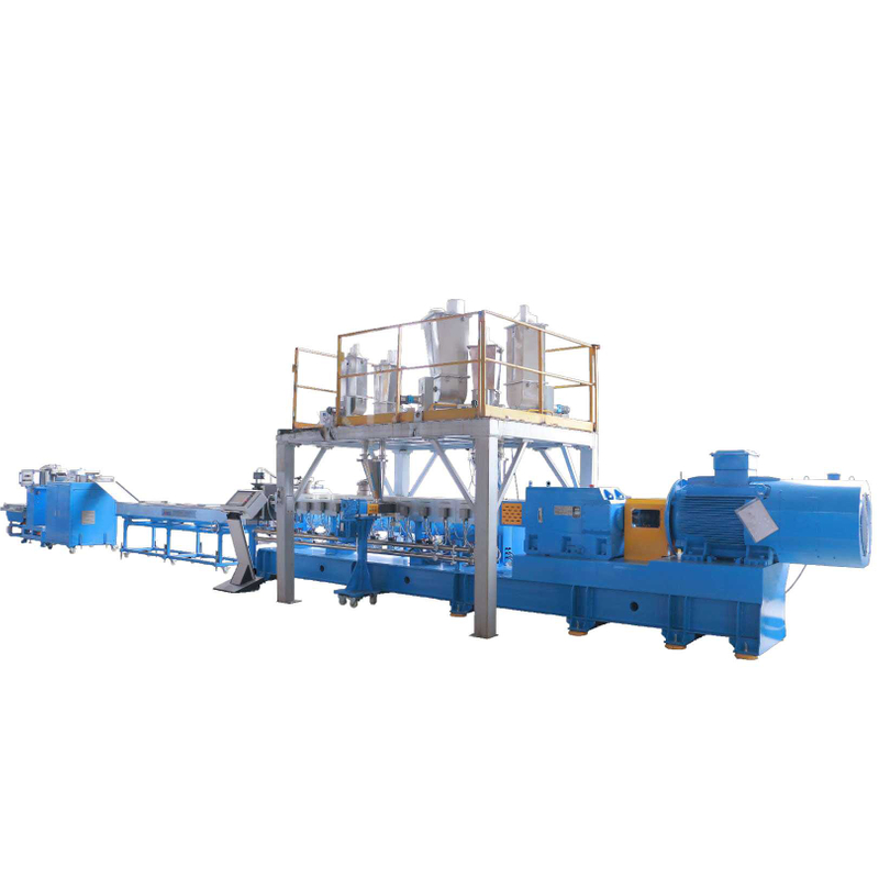
The CJWH Twin-Screw Extruder Pelletizing Line serves compounding and recycling applications. The model range extends from CJWH25 to CJWH135.
This range covers defined processing duties: recycling, masterbatch production and material modification. Those applications place different demands on formulation, feeding and the chosen screw configuration, so the broad model range needs a clearly defined project objective. Eleven sizes provide screw diameter and other selection data, while L/D choices and paired speed, power and capacity entries require careful interpretation. Buyers should compare complete selected arrangements rather than combine values from different alternatives into a new specification. The intended additives and material properties also belong in the enquiry, with downstream pellet requirements stated separately. A useful proposal connects the formulation, selected extrusion configuration and pellet-handling scope. The range offers a basis for that discussion without implying that one standard setup delivers every listed compounding or recycling application.
CJWH Twin Screw Extruder Pelletizing Line
The product identifies recycling pelletizing, color masterbatch, functional masterbatch, filling masterbatch, biodegradable materials and engineering plastic modification. Define one formulation and process duty at a time. A broad application list does not establish identical output for all compounds.
Identify the principal duty before comparing sizes. Recycling a prepared polymer stream differs from producing a formulated compound or masterbatch. State the required material properties and ingredients so the proposal can address the intended process rather than treat the application list as one universal equipment configuration.
Eleven rows list screw diameters from 26 mm to 132.5 mm. This range supports comparison across different production scales. Select the size around formulation, output requirement and mixing duty rather than a diameter-only rule.
The eleven sizes offer a broad dimensional comparison, but screw diameter alone does not complete selection. Review it alongside the chosen L/D, speed, motor and output entry. The configuration should be stated as a matched set so the quoted equipment can be assessed against the actual processing duty.
Every row lists L/D 24~68. Agree the selected process length and screw configuration for the formulation. The published range represents configuration scope, not multiple barrel lengths installed simultaneously on one machine.
The available L/D range describes configuration choices rather than a single supplied ratio. Discuss the intended formulation and process requirements before choosing the arrangement. The final proposal should identify the selected value directly, keeping the catalogue's available range separate from the actual equipment specification.
Model | Diameter | L/D | Screw speed | Motor power | Torque per shaft | Specific torque | capacity range |
CJWH25 | 26 | 24~68 | 600 | 11 | 87 | 9 | 20~40 |
CJWH35 | 35.7 | 24~68 | 600 | 30 | 235 | 9 | 75~150 |
CJWH40 | 41.3 | 24~68 | 600 | 45 | 357 | 9 | 110~220 |
CJWH52 | 51.7 | 24~68 | 600 | 90 | 692 | 9 | 220~440 |
CJWH65 | 62.7 | 24~68 | 600 | 160 | 1224 | 9 | 400~800 |
CJWH75 | 71.4 | 24~68 | 600 | 250 | 1990 | 9 | 550~1100 |
CJWH85 | 81.4 | 24~68 | 600 | 315 | 2713 | 9 | 800~1600 |
CJWH95 | 93.5 | 24~68 | 600 | 500 | 4131 | 9 | 1250~2500 |
CJWH110 | 110.6 | 24~68 | 500 | 630 | 6346 | 9 | 1500~3000 |
CJWH120 | 120.6 | 24~68 | 500 | 900 | 8705 | 9 | 2250~4500 |
CJWH135 | 132.5 | 24~68 | 400 | 900 | 11586 | 9 | 2250~4500 |
Most rows show two screw-speed and motor-power entries within each cell. Preserve the alternatives and confirm their pairing in the technical proposal. The values should not be added together as though both drives operate on the same configuration.
Dual values need to be preserved as alternatives until their relationship is confirmed. Do not combine one speed with a different power or capacity entry to create a presumed arrangement. Ask for the selected pairing to be identified in the technical proposal so electrical and production planning use confirmed data.
The table lists torque per shaft and specific torque alongside capacity. CJWH75, for example, lists 1990 N.m per shaft and specific torque 9. Use these values as part of a complete extrusion comparison for the intended formulation.
The common specific-torque entry forms one part of the table. It should be reviewed alongside screw size and the selected operating arrangement, not converted into a guarantee for every formulation. Material ingredients and process requirements remain necessary to understand how a proposed configuration relates to the intended compound.
State base polymer, fillers, additives and the desired pellet properties. Their proportions and physical forms matter when planning the feeding arrangement. Define required material streams in the proposal rather than assuming every dosing device is included.
A formulation enquiry should identify each component and how it will be supplied. Add required proportions and the target compound properties, while distinguishing existing feeding equipment from new supply. This gives the equipment review a clear basis without implying that every additive-handling device is already included in the line.
The JWM WPC pelletizing line addresses wood-plastic compounds. The SJZ PVC conical twin-screw line provides a PVC-focused route. Compare these specialized options with CJWH when the formulation requires a more specific process discussion.
Material-specific ranges provide alternative starting points for a more defined application. Compare them using the same feed and desired output, with the process scope clearly stated. A PET, PVC or WPC route should not be considered interchangeable simply because all produce pellets through extrusion.
Provide DYUN's compounding team the formulation, throughput target and quality requirements. Include feeding points, utility constraints and preferred pellet handling. Confirm the selected speed-power-capacity option so the final specification is internally consistent.
Provide the formulation objective, material descriptions and output requirements, including the desired pellet handling. The selected speed, motor, capacity and screw arrangement should then be identified together. This makes the proposal reviewable and avoids treating the broad catalogue table as a fixed processing recipe.
The DYUN company introduction places its recycling equipment activities within JWELL. For CJWH projects, formulation data and the selected screw, drive and feeding configuration are needed to turn the wide model range into a defined compounding proposal.
For compounding projects, the manufacturer's proposal should follow the formulation objective and identify a matched equipment configuration. The selected screw, L/D, speed and motor data need to remain connected to the intended material duty. Feeding and pellet-handling boundaries then complete the scope for a meaningful purchase comparison.
 JWELL factory scene displayed on DYUN's company page.
Define the principal duty and formulation first, then review screw diameter, L/D and the selected speed, power and output arrangement. Recycling, masterbatch and material modification are different project contexts; one application list does not establish a universal supplied setup.
The table contains eleven sizes, with listed screw diameters from 26 to 132.5 mm. These dimensions support comparison, but selection also needs the intended material and the confirmed operating configuration rather than screw size alone.
No. Dual entries should be retained as listed alternatives until their pairing is confirmed. The technical proposal should state the selected speed, motor and output together. Combining unrelated entries can create an equipment specification that the source does not establish.
The listed 24–68 range provides configuration choices. The selected ratio should follow the intended formulation and process duty and be identified in the proposal. A range of available choices is different from the actual equipment arrangement being purchased.
Identify polymers, fillers or additives, required proportions and target compound properties. State how materials are supplied and the required pellet output. Separate existing dosing or feeding equipment from new supply so the extrusion and pellet-handling scope is clear.
Use the same formulation and output requirement, then compare the complete selected screw, L/D, speed and motor arrangement. Check feeding, cutting and collection scope as separate items. A matched configuration is more informative than the largest capacity figure from each catalogue.


