
- All
- Product Name
- Product Keyword
- Product Model
- Product Summary
- Product Description
- Multi Field Search
 English

Views: 0 Author: Site Editor Publish Time: 2026-10-17 Origin: Site


Over 350 million tons of plastic waste hit our global ecosystem annually. How do we process this massive volume efficiently? The answer lies on the factory floor. The foundational machinery of almost every successful recycling facility is the single screw extruder.
Many plant managers know what this equipment does on the surface. Raw waste goes in, and clean pellets come out. But truly understanding the underlying mechanics is a different story. Grasping these thermodynamic and physical concepts allows operators to optimize setups. You can slash energy consumption. You can significantly improve the quality of the final recycled pellets. This guide breaks down the core mechanics. We will explore critical components and demonstrate how mastering these dynamics transforms your production output.
Key Takeaways
Global mandates are pushing for higher Post-Consumer Resin content in new packaging. This industry shift demands recycling machinery that can handle inconsistent bulk densities and varying contamination levels. A single screw extruder is a robust continuous processing machine. It serves as the beating heart of the polymer recycling industry.
At its core, it utilizes a single rotating Archimedean screw housed within a precisely machined and heated metal barrel. Its primary function is straightforward but physically demanding. It melts, mixes, and pumps solid polymer materials into a continuous viscous fluid. This fluid is then forced through a die to create a specific shape.
On the factory floor, this equipment bridges the gap between raw waste and reusable raw material. You might feed it washed flakes, crushed rigid scraps, or densified films. The extruder phase-changes this chaotic mix into high-quality uniform plastic pellets. Having only one rotating shaft makes this equipment highly reliable. It is easier to maintain and extremely cost-effective compared to complex multi-screw alternatives.
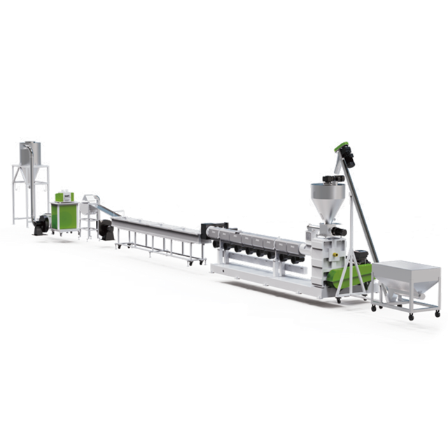
To fully optimize a production run, engineers must visualize the mechanics inside the closed barrel. Extrusion is not merely about applying heat until plastic turns to liquid. It is a complex thermodynamic and mechanical ballet. The screw is geometrically divided into three distinct zones. Each performs a specific engineering function as the material travels from the inlet to the die.
The journey begins when an operator or automated conveyor deposits raw plastic into the feed hopper. In this initial section, the screw flights are deep. The channel volume is at its maximum. The primary goal here is capturing solid plastic flakes and conveying them forward efficiently. Premature melting must be avoided at all costs.
From a physics perspective, this zone operates entirely on the principle of friction. The plastic must stick to the inner wall of the stationary barrel. Simultaneously, it must slip against the polished surface of the rotating screw. If friction against the screw becomes too high, the material simply rotates in place. Engineers call this frustrating phenomenon bridging. To combat this, the barrel in the feeding zone features water cooling jackets. This maintains a high coefficient of friction on the barrel wall and ensures a steady volumetric flow rate.
As the solid plastic is forcefully pushed forward, it enters the transition zone. This is where the most dramatic physical transformation occurs. The root diameter of the screw gradually increases. This design choice causes the channel depth between the screw and the barrel to shrink.
This decreasing volume aggressively compresses the plastic. As the material is squeezed, trapped ambient air is forced backward and expelled through the hopper. The plastic is subjected to intense mechanical shear. External heater bands provide essential thermal energy. However, up to 80 percent of the heat required to melt the plastic is generated by internal friction. Polymer molecules rub against each other and the metal surfaces under immense pressure. A melt pool forms. It gradually breaks down the solid bed of plastic until the entire mass converts into a flowing liquid.
The final section of the screw is the metering zone. By the time the polymer reaches this stage, it should be completely free of solid particles. The channel depth here is shallow and remains constant across the remaining flights.
Thermal homogenization is the core objective. This zone ensures the melt achieves a uniform temperature and viscosity. It also builds sufficient head pressure to push the heavy fluid through the downstream screen changer and die head. The precise balance of drag flow and pressure flow dictates the final output rate. Drag flow pulls material forward via rotation. Pressure flow pushes material backward due to die resistance.
Seamless execution relies on heavy-duty mechanical components working in perfect harmony. When investing in a reliable plastic pelletizing machine, understanding these parts is crucial for long-term maintenance and profitability.
The Hopper: This is the intake funnel for raw materials. For lightweight materials like LDPE film flakes, hoppers feature forced-feeding crammers. These artificially increase bulk density before the material hits the screw.
The Barrel and Heaters: This stationary thick-walled metal cylinder houses the screw. Modern designs utilize multiple zones of electrical heating bands and cooling fans. This allows operators to precisely manipulate the temperature profile. Bimetallic alloys are frequently specified to resist abrasive wear from contaminated scraps.
The Screw: The absolute core of the machinery. It is machined from high-yield steel and coated with wear-resistant treatments. The specific geometry dictates the success of the melt.
The Gearbox and Motor: Overcoming the massive rotational resistance of solid polymers requires a high-torque gearbox. Heavy-duty thrust bearings absorb the immense backward pressure generated during extrusion.
Beyond simple mechanics, engineering success hinges on critical metrics like the Compression Ratio. Mathematically, this is the ratio of the flight depth in the feed zone to the flight depth in the metering zone. It dictates exactly how aggressively the plastic is squeezed.
Different polymers inherently demand different compression ratios. Rigid crystalline PET requires a gentle compression, typically around 2.0:1, to avoid excessive shear degradation. Fluffy LDPE film needs highly aggressive compression, up to 4.5:1, to densify the material and squeeze out trapped air. Using the wrong ratio inevitably leads to catastrophic processing failures. You might see foaming at the die or shattered molecular chains.
Equally important is the Length to Diameter ratio. A higher L/D ratio provides a longer barrel. This increases the residence time of the plastic, allowing for thorough melting and highly stable pumping pressure.
When upgrading a facility, engineers frequently debate between single and twin-screw technologies. Both possess distinct mechanical advantages. Their application depends entirely on your feedstock and end goals.
| Feature | Single Screw Extruder | Twin Screw Extruder |
|---|---|---|
| Mechanism | Friction and drag flow | Positive displacement |
| Primary Application | Standard recycling and pelletizing | Complex compounding and devolatilization |
| Maintenance Cost | Low | High |
| Mixing Capability | Moderate | Excellent |
| Pressure Generation | Very High | Moderate |
Single screw setups are exceptional at building the high head pressures required to push viscous melts through dense filtration screens. This makes them the undisputed champion for standard recycling tasks.
A one-size-fits-all approach simply does not exist in professional recycling. The true value of this machinery emerges when it is tailored to specific rheological properties.
Polypropylene and Polyethylene dominate the municipal waste stream. When dealing with rigid regrind from bottles or pipes, the equipment must handle high throughputs while maintaining rock-solid pressure stability. For these rigorous applications, operators rely on a dedicated PP PE Pelletizing Line. These advanced setups utilize optimized screw geometries with specific L/D ratios, often reaching 30:1 or 36:1. This efficiently melts rigid polyolefins without degrading their molecular weight. The resulting pellets retain the high tensile strength required for downstream injection molding.
Polyethylene Terephthalate presents a completely different thermodynamic hurdle. PET is highly hygroscopic. If extruded with residual moisture, it undergoes hydrolytic degradation. The final product turns brittle and useless. When configuring a specialized Plastic granulation line for PET, the extruder requires heavy modification. These units feature specialized low-shear barrier screws and extensive vacuum venting zones along the barrel. These critical modifications extract moisture and volatile gases during the melting phase. This safely preserves the Intrinsic Viscosity of the polymer.
Even with top-tier machinery, operators will inevitably encounter processing anomalies. Diagnosing these issues through the lens of extrusion physics allows for rapid corrective actions.
Surging: This manifests as cyclical fluctuations in the output rate at the die. It leads to uneven pellet sizes. Surging is almost always a solids-conveying issue in the feeding zone. If lightweight material bridges in the hopper, the screw is starved. Verify the cooling water flow to the feed throat to prevent premature melting. Ensure forced-feeders are synchronized with the main screw RPM.
Poor Melt Quality: If the extruded strands contain solid lumps or gels, the plastic is not achieving thermal homogenization. The polymer is passing through the transition zone too quickly. Decreasing the screw RPM increases residence time. This allows the material to absorb more heat. Checking for blown heater bands is also a necessary first step.
Overheating and Degradation: When the melt exits the die discolored or smoking, the polymer chains are breaking down. Excessive shear friction in the metering zone is usually the culprit. Lowering the screw speed reduces mechanical friction. Heavily clogged screen packs also create excessive backpressure. Executing a screen change often resolves the temperature spike immediately.
The elegance of the single screw extruder lies in its brilliant combination of mechanical simplicity and complex thermodynamic efficiency. Leveraging precise screw geometries to feed, compress, melt, and pump polymer makes this technology the backbone of the global circular economy.
Understanding the delicate interplay between friction, shear heat, and compression ratios is the first step to running a highly profitable operation. Selecting the correct screw design and barrel configuration dictates the market value of your final product. Take the time to evaluate your current material streams carefully.
Ready to upgrade your recycling infrastructure for maximum yield and energy efficiency? Explore the comprehensive range of high-performance extrusion solutions at Jwell to find the exact machinery tailored to your production demands.
The L/D ratio stands for Length to Diameter ratio. It is a critical engineering specification describing the length of the flighted section divided by its outside diameter. A higher L/D ratio provides a longer barrel. This increases the residence time of the plastic, allowing for more thorough melting and highly stable pumping pressure.
While the basic framework handles most thermoplastics, the internal screw design must be strictly customized. Different plastics possess distinct melting points and friction coefficients. A screw designed with a high compression ratio for fluffy PE film will cause severe thermal degradation if used for rigid PET. The geometry must always match the thermodynamics of the specific material.
Cooling methods depend entirely on the polymer type and desired pellet shape. Water Ring Pelletizing cuts the melt immediately at the die face and throws it into a circulating water ring. Strand Pelletizing extrudes long strands through a water cooling bath before chopping them. Underwater Pelletizing submerges the die face completely, cutting the polymer directly in the water to create perfectly spherical pellets.
Operating temperatures vary drastically based on the specific polymer being processed. Polyolefins like PE and PP typically run between 180 and 240 degrees Celsius. Engineering plastics like PET or Nylon require much higher thermal profiles, often exceeding 270 degrees Celsius. Operators must precisely calibrate the heating bands across different barrel zones to match the melting point of the feedstock without causing thermal degradation.
Output capacity is primarily determined by the screw diameter, channel depth in the metering zone, and the rotational speed. Engineers calculate the theoretical output by balancing the drag flow moving forward against the pressure flow pushing backward from die resistance. In real-world applications, bulk density of the raw material and the efficiency of the feeding zone also heavily influence the final kilogram-per-hour yield.


