
- All
- Product Name
- Product Keyword
- Product Model
- Product Summary
- Product Description
- Multi Field Search
 English

Views: 0 Author: Site Editor Publish Time: 2026-10-19 Origin: Site


Are your compounding lines suffering from poor material mixing and rapid internal wear? As a process engineer, I see plant managers face these dual frustrations daily. Understanding the exact mechanical behavior of your machinery is the first line of defense against costly unplanned production downtime.
In this technical breakdown, we look at the internal workings of modern extrusion equipment. We will explore the mechanical stages, compare equipment configurations, and share actionable strategies to optimize your system for maximum output and profitability.
A twin screw extruder is a heavy-duty electromechanical processing device utilized extensively across the plastics and chemical industries. At its core, the machine consists of two parallel rotating shafts housed within a closely fitted heated barrel. Unlike basic forming machines, this highly engineered equipment performs continuous chemical and physical reactions under precise temperature and pressure controls.
The fundamental concept relies on the dynamic interaction between the two rotating shafts and the internal barrel wall. Their geometric design forces polymer resins and chemical additives forward while subjecting them to intense mechanical shear. This harsh internal environment facilitates the rapid melting and homogeneous blending of distinct raw materials into a single uniform matrix.
Operating this machinery requires a high degree of technical proficiency. Modern technicians must continuously monitor digital melt pressure transducers and adjust gravimetric feed rates on the fly. They also regulate shaft speeds to ensure the polymer melt remains perfectly stable. Even a minor deviation in these parameters can lead to immediate material degradation or inconsistent pellet geometry.
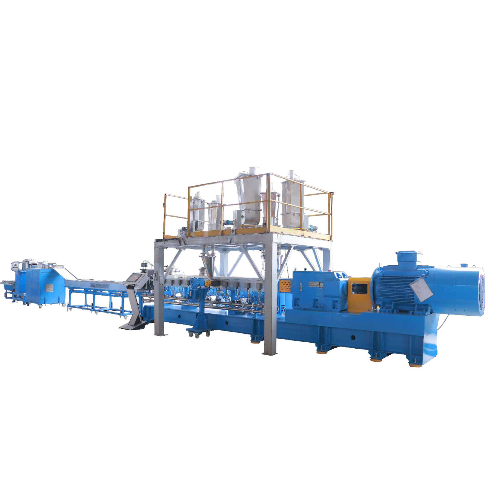
Understanding the mechanical sequence of this equipment is essential for plant managers looking to optimize their production lines. The internal process is divided into five distinct stages. Each stage is engineered to perform a specific function on the polymer matrix.
The process begins at the intake zone. Raw materials like base resins, liquid additives, colorants, and mineral fillers enter the main hopper. Industrial setups typically employ advanced loss-in-weight feeders. These intelligent devices meter the raw materials with extreme precision. To prevent blockages, the intake section features deep flights designed to accommodate high volumes of solid material and convey it rapidly away from the feed throat.
As the material moves forward, it enters the transition zone. Here, rotation begins to aggressively compress the polymer. While external electrical heater bands provide initial thermal energy, the vast majority of the melting process is driven by mechanical friction. The incredibly tight clearances between the rotating metal and the barrel wall generate intense internal heat. This transitions the solid plastic pellets into a highly viscous molten state.
Once fully melted, the material enters the mixing zone. This section utilizes specialized modular elements, primarily kneading blocks and reverse-pitch components. These parts subject the polymer melt to immense shear forces. Dispersive mixing shatters solid agglomerates into microscopic particles. Concurrently, distributive mixing ensures these tiny particles are spread evenly throughout the polymer matrix.
During the intense melting phases, ambient moisture, trapped air, and volatile organic compounds are released from the raw materials. If left trapped in the melt, these expanding gases cause voids and severe structural weaknesses in the final product. To combat this, the barrel features a venting zone open to a high-capacity vacuum system. The specialized profile spreads the melt thinly. This drastically increases its surface area and allows the vacuum to aggressively extract unwanted gaseous impurities.
In the final stage, the machinery acts as a powerful continuous pump. It builds sufficient pressure to force the purified homogeneous polymer melt through a precision-machined die head. As the glowing material exits the die in the form of continuous strands, it is immediately quenched. Finally, the solidified plastic is cut into uniform marketable pellets by a plastic pelletizing machine, ready for packaging or further downstream manufacturing.
To evaluate capital equipment investments effectively, buyers must intimately understand the physical architecture of the machinery. A standard line is built upon three critical interconnected subsystems.
The drive system acts as the beating heart of the extruder. It consists of a high-capacity AC motor coupled directly with a heavy-duty reduction gearbox. The gearbox must evenly distribute massive mechanical torque to two separate parallel shafts while maintaining absolute rotational synchronization. High torque capacity allows the machine to process highly viscous engineering materials and heavy filler loads without stalling. For instance, high-end equipment often supports a specific torque rating of up to 11.5 Nm/cm³, enabling high-fill compounding with ease.
Modern industrial extruders utilize a highly modular barrel design. Multiple individual sections are bolted tightly together. This modularity allows process engineers to customize the length-to-diameter ratio based on their specific processing needs. Ratios typically range from 32:1 to over 52:1 depending on the application. Each independent barrel section is equipped with its own electrical cast-in heaters and internal liquid cooling channels. This creates precise temperature control zones.
Unlike simple agricultural augers, the internals are not solid single-piece metal shafts. Instead, they are assembled by sliding various modular parts onto a central splined shaft. This brilliant design allows engineers to map out a custom profile. Elements include forward conveying blocks for moving material rapidly, wide kneading blocks for aggressive melting, and reverse elements to create localized melt seals.
When selecting new processing equipment, decision-makers must choose between two primary mechanical configurations. This fundamental choice dictates the machine's processing capabilities and its ideal factory applications.
In a co-rotating configuration, both shafts rotate in the exact same direction. This design creates a remarkably high-shear environment and features a unique self-wiping mechanism. The flight of one shaft continuously cleans the root of its partner. Co-rotating machines operate at exceptionally high speeds, often exceeding 600 RPM, offering unparalleled mixing efficiency. They remain the undisputed industry standard for advanced recycling where thorough homogenization is the primary goal.
In contrast, a counter-rotating setup features shafts turning in opposite directions. This mechanism creates a low-shear, low-friction environment. Raw materials are essentially trapped in isolated chambers and pumped forward with minimal internal mixing. Because they generate very little frictional heat, counter-rotating extruders are primarily utilized for processing highly heat-sensitive materials like PVC.
Plant managers frequently face the difficult decision of whether to invest in a single or dual-shaft system. While single-shaft extruders are mechanically simpler and noticeably cheaper upfront, they serve a fundamentally different purpose on the manufacturing floor. To make equipment selection clear, I always advise my clients to look at this practical comparison matrix based on real-world engineering demands.
| Feature | Single Screw Extruder | Twin Screw Extruder |
|---|---|---|
| Primary Function | Melting and conveying pre-mixed materials. | Intense compounding, mixing, and devolatilization. |
| Mixing Capability | Low. Relies mostly on drag flow. | Exceptional. Offers both dispersive and distributive mixing. |
| Material Flexibility | Struggles with high filler loads or powder additives. | Easily handles complex recipes and up to 80% mineral fillers. |
| Self-Cleaning | Poor. Requires teardowns or heavy purging. | Excellent. Co-rotating design continuously wipes the barrel clean. |
Specifically, if your production involves blending multiple additives or managing high filler loads, the intermeshing dual-shaft system is the only logical choice. A single-shaft machine will simply lose structural integrity in the melt phase when pushed beyond its intended forming capabilities.
Looking at recent market analyses and equipment developments, the manufacturing landscape is rapidly evolving. The global legislative push toward sustainability is forcing equipment manufacturers to adapt quickly. There is a massive industry-wide surge in demand for systems capable of handling shear-sensitive bioplastics like PLA and PBAT. These advanced eco-materials require extremely precise localized shear control.
Furthermore, the transition towards circular economy models has made high-efficiency melt filtration and vacuum degassing non-negotiable. Modern processing facilities are increasingly integrating Industrial Internet of Things sensors directly into the barrels and gearboxes. This digital shift allows plant operators to transition from reactive troubleshooting to predictive maintenance. Monitoring real-time torque spikes, vibration harmonics, or subtle temperature deviations before a catastrophic mechanical failure occurs is now the industry baseline.
Industrial manufacturing requires precision, repeatability, and high continuous throughput. Mastering Industrial plastic pelletizing relies heavily on the versatility of the co-rotating mechanism. Because these machines offer superior capabilities, manufacturers across various sectors leverage this technology to process a wide array of polymers, chemical additives, and reinforcing fillers.
In color masterbatch manufacturing, achieving perfect pigment dispersion is the absolute primary operational objective. Raw pigments naturally tend to form cohesive stubborn agglomerates. These clumps can cause severe color streaks or structural weaknesses in the final molded plastic product. The high shear forces generated by specialized kneading blocks effectively break down these solid agglomerates. This mechanical action ensures the pigment is uniformly distributed throughout the carrier resin, guaranteeing absolute color consistency across massive production batches.
Engineering plastics often require the complex blending of base resins with reinforcing agents like glass fibers, talc, or chemical flame retardants. This compounding process demands a delicate balance of mechanical forces. The equipment must provide enough shear energy to melt the polymer matrix but not so much that it crushes the structural integrity of the reinforcing fibers. Integrating a high-torque Twin screw pelletizing line into your facility allows for this modular flexibility. Operators can utilize downstream side feeders to introduce fragile glass fibers later in the melt zone, enabling rapid transitions between different engineering compound recipes.
Post-consumer and post-industrial recycling present incredibly unique processing challenges. This is primarily due to the heavy presence of ambient moisture, volatile organic compounds, and residual ink contaminants. Advanced equipment excels in this specific application due to its aggressive surface renewal and high-efficiency vacuum degassing capabilities. As the polymer melt is continuously folded and stretched, trapped gases are forced to the surface and extracted. This significantly upgrades the mechanical quality of the reclaimed material, making it suitable for high-end applications like bottle-to-bottle PET recycling.
When evaluating capital equipment upgrades, plant managers must objectively weigh both the operational benefits and the ongoing maintenance requirements of the machinery to maintain peak profitability.
The primary advantage of this equipment is its high continuous output combined with precise localized control over material residence time. Unlike traditional single-shaft systems where molten material can easily stagnate and burn, the intermeshing profile creates a powerful self-wiping effect. This prevents polymer degradation and ensures a highly narrow residence time distribution. Consequently, manufacturers benefit from consistent pellet quality, uniform melt temperatures, and significantly reduced scrap rates.
Despite their robust industrial design, these machines are susceptible to specific operational hazards. The most prominent challenge is the abrasive wear and tear of the internal elements. Processing highly filled compounds, especially those containing titanium dioxide or abrasive glass fibers, can rapidly erode standard steel components. To mitigate this, manufacturers must invest in specialized metallurgy such as bimetallic barrel liners and tungsten carbide-coated wear parts.
Another critical precaution is preventing external metal contamination. If tramp metal enters the feeding hopper, it can cause immediate catastrophic damage to the intermeshing shafts and the main transmission gearbox. Installing high-intensity magnetic separators at the feeding throat is a mandatory industrial safeguard.
Achieving maximum mechanical efficiency from your compounding line requires more than just turning on the power. Operators and process engineers must continuously fine-tune the operational parameters to match the specific thermal properties of the polymer.
The modular layout is the undisputed heart of the compounding process. There is no universal setup; it must be tailored precisely to the specific resin. A standard geometric profile consists of conveying elements to move raw material, kneading blocks for melting, and reverse pitch elements to create melt seals. If the internal melt temperature is running dangerously high, replacing aggressive wide kneading blocks with milder distributive mixing elements can drastically reduce excessive shear heat.
A proactive data-driven maintenance schedule is non-negotiable. The gearbox transmits immense rotational torque and requires regular oil sampling alongside scheduled fluid changes to prevent catastrophic thrust bearing failure. Operators should be trained to listen for unusual gear whine. Additionally, maintenance engineers must routinely measure the physical clearances between the flights and the internal barrel wall. As this clearance naturally increases due to abrasive wear, forward pumping efficiency drops.
Proper temperature management involves carefully balancing the external electrical heater bands with the internal frictional heat generated by rotation. In many high-speed applications, the polymer generates more than enough internal shear heat to remain fully molten. By fine-tuning the internal chilled water cooling zones, operators can prevent polymer degradation, minimize off-gassing, and dramatically lower overall electrical energy consumption.
These advanced systems operate on a strict starve-fed principle. This means the total throughput is entirely dictated by the upstream feeders, not the rotational speed. Inconsistent material feeding is the primary root cause of surging at the extrusion die head. Utilizing highly accurate loss-in-weight feeders ensures the mass flow rate remains perfectly stable regardless of bulk density variations. This feeding stability is the absolute secret to producing uniform pellets and preventing frustrating strand breakage during the water cooling phase.
Mastering the mechanics of your extrusion equipment is vital for modern manufacturing success. This deep technical knowledge empowers plant managers to improve production yields, troubleshoot defects rapidly, and drastically reduce unplanned downtime. Proper setup ensures your equipment runs at peak efficiency, while selecting the correct configuration maximizes your overall output quality.
Always prioritize rigorous data-backed maintenance schedules to extend your machinery's lifespan. By understanding the intricate balance of shear, temperature, and material flow, you can transform your compounding line into a highly profitable reliable asset.
Ready to upgrade your compounding and recycling capabilities? Visit Jwell Machinery to explore industry-leading extrusion solutions tailored to your exact production demands.
Yes, they are highly effective and increasingly preferred for advanced industrial plastic recycling operations. Unlike traditional single-shaft machines, these systems offer exceptional degassing and melt-filtration capabilities. When recycling post-consumer materials like PET bottles or heavily printed packaging films, the polymer is often heavily contaminated with moisture and volatile organic compounds. The intermeshing design continuously renews the surface of the polymer melt, exposing these trapped gases so they can be efficiently extracted through high-vacuum venting ports.
The operational lifespan varies dramatically based on the specific polymers and chemical additives being processed. When running standard unfilled commodity plastics like polyethylene or polypropylene, high-quality steel elements can easily last several years with minimal mechanical wear. However, when compounding highly abrasive materials such as glass fibers or titanium dioxide, the wear rate accelerates significantly. In these harsh environments, standard elements may require replacement every 6 to 12 months. Investing in bimetallic or tungsten carbide coatings extends this lifespan considerably.
Surging manifests as an inconsistent and pulsating flow of molten plastic at the die head and is a common operational challenge. In a starve-fed system, surging is most frequently caused by inconsistent raw material feeding. If the gravimetric feeders are bridging or losing calibration, the mass flow into the barrel fluctuates, causing severe pressure variations. Another common cause is an improper internal configuration failing to create a proper melt seal before the vacuum venting zone, which disrupts the forward conveying pressure.
Understanding this mechanical distinction is critical for optimizing complex formulations. Dispersive mixing involves applying high shear stress to physically break down cohesive solid clumps, such as color pigment agglomerates, into microscopic particles. This requires intense mechanical force. Distributive mixing is the process of spreading those broken-down particles evenly throughout the entire polymer matrix without necessarily reducing their physical size further. Advanced extruders excel because their modular profiles can be engineered to deliver optimal levels of both simultaneously.
The Length-to-Diameter ratio determines the residence time and the amount of processing space available for melting, mixing, and venting. A shorter L/D ratio, such as 32:1, is often sufficient for basic compounding and heat-sensitive materials. Conversely, a longer L/D ratio, like 48:1 or 52:1, provides the extended residence time required for complex reactive extrusion, multiple downstream feeding stages, and aggressive vacuum devolatilization of heavily contaminated recycled plastics.
Specific torque is a critical performance indicator that defines how much rotational power the gearbox can deliver to the shafts relative to their center distance. High specific torque equipment allows engineers to run the machine at higher fill levels and lower RPMs while maintaining the same throughput. This results in significantly lower melt temperatures and reduced polymer degradation, making it ideal for processing highly viscous engineering plastics and sheer-sensitive compounds.


