
- All
- Product Name
- Product Keyword
- Product Model
- Product Summary
- Product Description
- Multi Field Search
 English

Views: 0 Author: Site Editor Publish Time: 2026-07-25 Origin: Site


Miscalculating conveying distance is the leading cause of throughput bottlenecks, material degradation, and premature equipment failure in plastics processing facilities. Facility managers frequently underestimate the impact of vertical lifts and pipe bends, leading to under-sized vacuum pumps, excessive conveying velocities, and the generation of dust or "angel hair" (streamers) in the resin supply. Establishing the correct conveying distance requires moving beyond linear measurements to calculate "equivalent distance," selecting the appropriate conveying phase, and aligning system specifications with the output of your plastic pelletizing system. Relying on basic floor plans to size a pneumatic transfer line guarantees operational headaches. You must account for the physics of airflow, the friction of the pipe walls, and the fragility of the specific polymer being moved. A properly engineered layout ensures continuous material flow, protects pellet integrity, and maximizes the lifespan of your pneumatic components.
A vacuum conveying system for plastic pellets operates on the principle of negative pressure differentials. A vacuum pump located at the destination point removes air from the enclosed pipe network, creating a lower pressure zone. Atmospheric pressure at the material source then pushes air into the system, creating an airflow velocity capable of entraining and transporting bulk solids. The pellets are suspended in this airstream and carried to the receiver. However, this process is highly sensitive to the physical layout of the piping.
As routing length increases, friction against the pipe walls reduces the effective pressure differential. This degradation of vacuum over distance means you need higher initial vacuum levels to maintain target air velocities at the pickup point. If the vacuum pump lacks the capacity to overcome this cumulative resistance, the air velocity drops below the saltation velocity—the minimum speed required to keep pellets suspended. When this happens, pellets fall out of the airstream, dragging along the bottom of the pipe, eventually causing a complete line blockage.
The plastics industry frequently relies on high-speed dilute-phase conveying over long distances because the initial equipment costs are lower and the systems are relatively simple to operate. In dilute phase, pellets are suspended in a high-velocity airstream, typically moving between 4,000 and 6,000 feet per minute. Despite its popularity, pushing material at these speeds over long distances introduces severe operational issues, primarily dust generation and frictional heating.
There is a direct correlation between excessive distance, high velocity, and material degradation. When plastic pellets travel at high speeds through long pipe runs, they constantly impact and rub against the pipe walls. This friction generates heat. For softer polymers or materials with lower melting points, this frictional heating causes the outer layer of the pellet to melt slightly and smear against the pipe wall. As these smears build up and peel off, they form long, thin strands known as "angel hair" or streamers. Simultaneously, the constant impacts chip away at the pellets, creating fine dust. Both angel hair and fines clog filters, jam rotary valves, and cause defects in the final molded or extruded products.
Beyond material degradation, long-distance, high-velocity conveying accelerates the abrasive wear of system components. Elbows bear the brunt of this impact, as the material is forced to change direction rapidly. Rotary airlock valves and receiver bodies also suffer from the constant bombardment of high-speed pellets. Abrasive wear leads to premature component failure, vacuum leaks, and costly downtime for maintenance and replacements.
| Conveying Velocity (FPM) | Material Degradation Risk | Component Wear Rate | Typical Application |
|---|---|---|---|
| Below 3,000 | Low (Minimal dust/angel hair) | Low | Dense phase, fragile materials |
| 3,000 - 4,500 | Moderate | Moderate | Standard dilute phase, short distances |
| 4,500 - 6,000 | High (Significant angel hair risk) | High (Frequent elbow replacement) | Long distance dilute phase (Not recommended) |
| Above 6,000 | Severe (Unacceptable fines generation) | Extreme | Poorly designed or oversized systems |
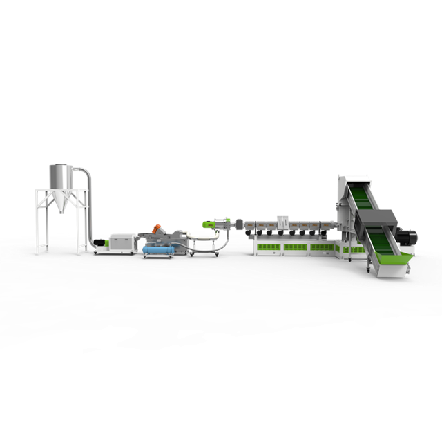
Relying on simple linear floor-plan measurements is a guaranteed way to undersize a pneumatic conveying system. The actual system resistance must be calculated using the "equivalent length" framework. This engineering metric translates every vertical lift, elbow, and directional change into an equivalent length of straight, horizontal pipe. This provides a true representation of the workload the vacuum pump must overcome.
Vertical piping creates a massive multiplier effect on system resistance. When moving material horizontally, the air velocity only needs to overcome the friction of the pipe and the inertia of the pellets. However, when moving material vertically, the system must continuously fight gravity. A standard engineering rule of thumb is that one foot of vertical lift demands the same energy as two feet of horizontal run. Therefore, a 20-foot vertical lift adds 40 feet of equivalent distance to your calculation.
Directional changes, specifically elbows and bends, add substantial resistance. When pellets hit an elbow, they lose momentum and drop out of suspension. The system must expend significant energy to re-accelerate the material back to conveying speed after the bend. A single standard 90-degree elbow can add the equivalent of 20 linear feet of pipe resistance. If you have a system with 20 feet of vertical pipe, 20 feet of horizontal pipe, and two 90-degree elbows, the linear distance is 40 feet, but the equivalent distance is 100 feet (40 for vertical + 20 for horizontal + 40 for elbows).
The sequence of these components also matters. This is known as the pneumatic layout strategy. Vertical lifts should always be positioned as close to the material feed point as possible. If you place a vertical lift at the end of a long horizontal run, the air velocity will have already degraded due to friction. The sudden demand to overcome gravity at the end of the line will cause a terminal velocity drop, leading to immediate line plugging. Pushing material up early in the run ensures the system has maximum pressure differential to handle the lift.
Minimizing equivalent distance requires practical layout strategies. Utilize long-radius sweeps instead of sharp, standard elbows. A long-radius sweep allows the material to change direction more gradually, reducing impact friction and pressure drop. Minimize overall directional changes by routing pipes as directly as possible, even if it requires suspending them from the ceiling rather than following the walls of the facility.
Selecting the right conveying phase is critical when dealing with extended equivalent distances. Dilute phase conveying is best suited for short to medium equivalent distances where high velocity does not compromise pellet integrity. In these applications, the friction is manageable, and the degradation risk remains low. However, its limitations become apparent over long runs. The high friction generated over hundreds of feet of pipe leads to unacceptable levels of material degradation and component wear.
For extreme distances, dense phase and wave conveying offer superior performance. These systems move plastic pellets in slow-moving waves or solid slugs rather than suspending them in a high-speed airstream. Dense phase systems can effectively transport material over distances up to 1,000 feet while maintaining velocities below 1,000 feet per minute. This slow movement drastically reduces friction.
The value influencing factors for dense phase systems include a higher initial capital expenditure, as they require specialized pressure vessels, precise air injection controls, and heavier-duty piping. However, this upfront cost is offset by significantly lower maintenance costs. Dense phase systems produce zero angel hair, drastically reduce dust generation, and extend the lifespan of elbows and valves. The reduction in dust also lowers the requirements and maintenance frequency for filtration systems.
| Feature | Dilute Phase (Vacuum) | Dense Phase (Pressure) |
|---|---|---|
| Material State | Suspended in airstream | Moving in waves or slugs |
| Air Velocity | High (4,000+ FPM) | Low (Under 1,000 FPM) |
| Distance Capability | Short to Medium (Up to 300 ft eq.) | Long to Extreme (Up to 1,000+ ft eq.) |
| Degradation Risk | High (Angel hair, dust) | Very Low |
| Capital Cost | Lower | Higher |
When evaluating pressure modes, you must contrast vacuum (negative pressure) systems with positive pressure systems. A vacuum system is ideal for drawing material from multiple pickup points to a single destination. It is clean, as any leaks draw air inward rather than blowing dust into the facility. However, vacuum systems are limited by atmospheric pressure; you can only pull a maximum of 14.7 psi of vacuum. This limits their effective conveying distance.
A positive pressure system is required for transferring high-tonnage materials over extremely long distances or to multiple destination silos. Positive pressure systems use blowers or compressors to push the material, allowing for much higher pressure differentials (up to 15 psi for blowers, and up to 100 psi for compressors in dense phase). This makes them capable of overcoming massive equivalent distances, albeit often with higher conveying velocities if used in a dilute phase setup.
Overcoming distance limitations requires precise equipment sizing, starting with the vacuum pump. Upgrading the vacuum pump to achieve a higher vacuum yield is often the primary method for achieving longer conveying distances and higher throughput rates without increasing the pipe diameter. A larger pump generates a greater pressure differential, allowing the system to maintain the necessary saltation velocity over a longer equivalent distance.
There is a strict mathematical relationship between pipe diameter, air volume (CFM), and material carrying capacity over distance. If you increase the pipe diameter to move more material, you must exponentially increase the CFM of the vacuum pump to maintain the same air velocity. Conversely, if you try to push too much material through a small pipe over a long distance, the pressure drop will exceed the pump's capacity, resulting in a plugged line. Proper sizing requires calculating the exact CFM needed to maintain velocity based on the specific equivalent distance and the bulk density of the plastic pellets.
Integration with the upstream equipment is critical. You must match the conveying system's pull rate with the continuous output of the pelletizing line. If the conveying system is undersized for the equivalent distance, it will not be able to move the pellets as fast as the extruder produces them. This leads to upstream backups, overflowing catch bins, and forced shutdowns of the extrusion line. Conversely, an oversized system pulling from a limited supply will cause system starvation, leading to erratic conveying, increased velocity, and severe material degradation.
When upgrading or installing a new transfer line, you must assess if a plastic pelletizing machine supplier has the in-house pneumatic engineering expertise to accurately calculate equivalent distances and system pressure drops. Many equipment vendors simply sell off-the-shelf loaders based on linear distance charts. This approach is dangerous for complex layouts. You need a partner who performs detailed calculations, factoring in bulk density, particle size, and the specific routing of your facility.
Buying pre-packaged, standardized vacuum loaders for complex, long-distance routing carries significant operational risks. These units are typically designed for short, straight runs next to the machine. Applying them to a 200-foot equivalent distance run with multiple elbows will result in immediate failure. Custom-engineered systems, designed by a specialized manufacturer, ensure that the pump, piping, and receivers are perfectly matched to the specific resistance of your layout.
Always request material flow testing in a supplier’s lab before finalizing a purchase. Send a sample of your specific polymer and have them run it through a test loop that mimics your calculated equivalent distance. This validation step allows you to verify degradation limits, check for angel hair formation, and confirm that the proposed pellet velocity will not damage your material. If a vendor refuses to perform flow testing, consider it a major red flag.
The most common implementation risk is line plugging and surging, directly caused by under-calculated equivalent distances. When the resistance is higher than anticipated, the air velocity at the end of the line drops below the saltation point. Pellets fall out of suspension, build up in the pipe, and eventually block the flow entirely. Surging occurs when the system partially clears a blockage, sending a massive, high-velocity slug of material into the receiver, which can damage equipment.
To mitigate plugging and surging, implement line-clearing valves at the pickup point. These valves allow the system to purge the line with clean air before shutting down, preventing material from settling in the pipes. Additionally, install variable frequency drives (VFDs) on the vacuum pumps. VFDs allow you to adjust the air velocity based on real-time line resistance, ensuring optimal flow without over-speeding the material.
Filter blinding is another significant risk. Increased dust generated from long-distance friction can quickly overwhelm standard receiver filters. When filters blind, the system loses suction, and conveying stops. To mitigate this, specify oversized filtration areas for any long-distance run. Implement automatic pulse-jet cleaning systems that use blasts of compressed air to clear the filters continuously during operation, preventing dust buildup.
Friction over long pipe runs generates severe static electricity hazards. Plastic pellets are highly insulative, and as they rub against the pipe walls, they build up a static charge. This can lead to material clinging to the pipes, erratic flow, and in severe cases, dangerous static discharges. Mitigate this risk by ensuring proper system grounding across all pipe joints and components. Use specialized conductive piping or install static eliminators inline to neutralize the charge as the material flows.
Audit your current facility layout immediately to calculate the true equivalent distance of your pneumatic lines, factoring in every vertical lift and elbow. Inspect your existing resin supply and receiver filters for signs of angel hair or excessive dust, which indicate velocity issues. Consult with a specialized pneumatic conveying engineer to perform a pressure drop analysis before purchasing or upgrading any vacuum pump sizes.
A: Equivalent distance is calculated by adding the linear horizontal piping, the linear vertical piping multiplied by a factor of two for gravity resistance, and the equivalent length of all elbows. A standard 90-degree elbow typically adds 20 feet of equivalent resistance to the total calculation.
A: Angel hair refers to long, thin strands of plastic that form when pellets melt slightly due to friction against pipe walls. This occurs during high-velocity conveying over long distances, causing the melted plastic to smear and peel off into streamers.
A: Dilute phase conveying relies on high air velocity to suspend pellets. Over long distances, this sustained high velocity exponentially increases friction, leading to severe material degradation, excessive dust generation, and rapid abrasive wear on pipe elbows.
A: Vertical piping requires significantly more energy to overcome gravity compared to horizontal runs. In engineering calculations, a vertical run is typically calculated as having twice the resistance of an equivalent horizontal run, drastically impacting pump sizing.
A: Wave conveying moves pellets slowly in dense, compact waves rather than suspending them at high speeds. This significantly reduces friction, completely prevents angel hair formation, and minimizes abrasive wear on system components over extreme distances.
A: VFDs allow operators to precisely control the speed of the vacuum pump motor. This enables real-time adjustments to air velocity based on line resistance, preventing material degradation from excessive speeds while ensuring enough force to prevent line plugging.


