
- All
- Product Name
- Product Keyword
- Product Model
- Product Summary
- Product Description
- Multi Field Search
 English

Views: 0 Author: Site Editor Publish Time: 2026-07-25 Origin: Site


Unplanned downtime from pipeline blockages drains facility resources rapidly. Maintenance labor hours compound while production halts entirely. Positive pressure and dense phase conveying setups often suffer severe line choking, causing material degradation and angel hair formation when moving temperature-sensitive or abrasive polymers. Negative pressure conveying offers a highly controlled alternative. This technical evaluation guides plant engineers and operations managers to determine if transitioning to a vacuum-based architecture resolves chronic blockage issues without creating new bottlenecks. We will examine the fluid dynamics of pellet transport, the mechanical differences between pushing and pulling materials, and the specific engineering requirements for sizing a reliable system. By understanding the root causes of line choking, facilities can implement targeted solutions that protect product integrity and maintain continuous throughput.
Pipeline blockages rarely happen instantly. They develop through a combination of poor fluid dynamics and material characteristics. Sudden drops in conveying air velocity allow suspended plastic pellets to fall out of the air stream. These pellets settle at the bottom of the horizontal pipe sections, creating a stationary layer that restricts the active flow area. As the cross-sectional area decreases, the local air velocity increases, but the overall system pressure drop spikes. Excessive material-to-air ratios overload the conveying phase. When operators attempt to push too much product through a line designed for a lower capacity, the air cannot maintain the necessary suspension velocity.
Friction-induced melting occurs when polymer pellets scrape against the interior walls of the pipe at high speeds. This friction generates localized heat. The heat slightly melts the surface of the pellet. The melted polymer transfers to the pipe wall, cools, and hardens. Over time, these microscopic deposits build up into thick layers, particularly in long horizontal runs and tight-radius elbows. Pellet breakage creates fine dust particles that behave differently than whole pellets in the air stream. Angel hair streamers accumulate at pipe bends and rotary valves. These long, thin strands of melted polymer wrap around internal components and act as nets, catching other pellets. These accumulations gradually reduce the internal pipe diameter. Eventually, the line chokes entirely, stopping all material flow and requiring immediate intervention.
Different polymer grades exhibit unique behaviors that contribute to blockages. Soft elastomers like TPU or TPE are highly susceptible to frictional melting and require extremely low conveying velocities. Rigid polymers like PET or polycarbonate are abrasive and can wear down pipe walls, creating rough surfaces that trap fines. Understanding the specific physical properties of the material being conveyed is the first step in designing a system that resists choking.
System failures carry heavy financial burdens that extend far beyond the immediate loss of production. Direct costs involve manual line dismantling. Maintenance teams spend hours on pipeline cleanout labor, often requiring specialized tools and elevated work platforms to access overhead lines. Equipment damage often occurs during forceful unblocking attempts. Workers sometimes use hammers on pipe exteriors to dislodge stubborn plugs, causing structural fatigue, denting, and eventual pipe failure. Replacing damaged rotary valves, diverter valves, or blown blower seals adds significant parts and labor expenses.
Indirect costs include severe cross-contamination risks during grade transitions. Residual pellets from a previous run mix with the new batch, altering the physical properties and color of the final product. Compromised pellet quality leads to rejected batches, customer complaints, and the need to reprocess or scrap tons of material. Overall yield reduction impacts the efficiency of the entire plastic pelletizing system. Recovering from a single severe blockage can consume an entire production shift, throwing off delivery schedules and forcing downstream extrusion or molding lines to sit idle.
Consider the labor sequence required to clear a severe positive pressure blockage:
Vacuum systems pull material using negative pressure, whereas positive pressure systems push material. Pulling material toward a collection vessel prevents severe material compaction. This compaction normally causes solid plugs in positive pressure lines. When a positive pressure system encounters resistance, the blower continues to push air, wedging the pellets tighter together until they form an immovable, solid mass. The pressure behind the plug builds until the blower relief valve pops or a component fails.
Negative pressure systems operate differently. If resistance increases, the vacuum simply slips past the material without packing it further. The maximum pressure differential is limited by atmospheric pressure, meaning the system physically cannot generate the massive forces required to compact pellets into a solid brick. Negative pressure systems allow complete pipeline cleanout. At the end of a conveying cycle, the feed valve closes while the vacuum pump continues to run for a few seconds. This sweeps the line entirely clean. No residual pellets remain in the line. This prevents cross-contamination and blockages in subsequent runs, making vacuum conveying ideal for facilities that run multiple colors or grades through the same equipment.
Air expands as it moves toward the vacuum source. This expansion results in lower velocities at the pickup point and higher velocities at the receiver end. Lower initial velocities ensure gentler product handling as the pellets accelerate into the air stream. Controlled velocities minimize friction against the pipe walls. They reduce pellet breakage and the generation of dust. This drastically cuts down the formation of fines and melted polymer buildup. Fewer fines mean fewer blockages and less strain on the filtration system.
In a vacuum setup, managing this velocity profile prevents the aggressive impacts that cause angel hair formation in standard pipe elbows. Engineers use specific calculations to ensure the terminal velocity at the end of the line does not exceed the degradation threshold of the polymer. For highly sensitive materials, specialized deceleration chambers or long-radius, shot-peened elbows are installed to further reduce impact forces. The inherent nature of expanding air under vacuum provides a cushioning effect that positive pressure systems lack.
Modern setups integrate vacuum sensors that monitor system pressure in real-time. They provide a vital fail-safe mechanism against choking. Operators define a high-level vacuum limit based on the normal operating parameters of the specific material. When the system crosses this limit, indicating an impending blockage or an overloaded line, it automatically stops the rotary valve or feed mechanism. This action allows the line to clear itself before a hard blockage forms.
A reliable vacuum conveying system for plastic pellets relies heavily on this automated regulation. By cutting off the material supply instantly, the vacuum pump can evacuate the remaining pellets in the pipe, restoring normal operating pressure without manual intervention. Once the vacuum level drops back to the safe zone, the control system automatically resumes feeding. This continuous, self-correcting loop maximizes throughput while virtually eliminating the risk of a catastrophic line plug.
Engineers often increase pipe size down the convey line. This practice, known as pipe stepping, manages air expansion effectively. As air moves closer to the vacuum pump, its volume increases. If the pipe diameter remains constant, the air velocity must increase to accommodate the larger volume. By stepping up the pipe diameter at calculated intervals, the system lowers terminal velocities and maintains optimal velocity profiles throughout the entire run.
Selecting appropriate pipe materials is critical for long-term reliability. Aluminum is lightweight and easy to install but can wear quickly with abrasive materials. Stainless steel offers excellent durability and corrosion resistance. Bend radii must match the specific plastic pellets handled. Long-radius elbows prevent severe impact angles, allowing pellets to glide through the turn rather than smashing into the outer wall. Proper sizing minimizes impact degradation and frictional heat. A stepped pipeline design ensures that as the air expands under vacuum, the increased pipe volume keeps the air velocity within the optimal conveying range, preventing both settling and excessive impact.
| Pipe Material | Wear Resistance | Internal Surface Finish | Best Application |
|---|---|---|---|
| Standard Aluminum | Low | Smooth | Soft, non-abrasive pellets (e.g., LDPE) |
| Stainless Steel (304/316) | High | Smooth to Polished | Abrasive or high-purity polymers (e.g., PC, Medical Grade) |
| Shot-Peened Stainless | High | Dimpled/Textured | Materials prone to angel hair formation |
| Ceramic Lined | Extreme | Hard/Smooth | Highly abrasive compounds (e.g., Glass-filled Nylon) |
The collection tank and filter receiver play critical roles in the overall health of the conveying architecture. They separate the conveying air from the material mixture before the air reaches the vacuum pump. Filter efficiency dictates system health. If dust and fines bypass the filter, they will enter the vacuum pump, causing rapid wear, overheating, and eventual failure. Reverse-pulse cleaning mechanisms keep filters clear during operation. Compressed air blasts periodically dislodge dust from the filter media, dropping it into the collection hopper.
Preventing fines from reaching the vacuum pump is mandatory. A blinded filter drops vacuum pressure and causes immediate line choking because the system can no longer pull enough air to maintain suspension velocity. Selecting the right filter media depends on the specific dust characteristics of your polymer. Spun-bond polyester is standard for general applications, while PTFE-coated membranes are required for ultra-fine or sticky dust. Regular inspection of the filter housing seals and the pulse-jet diaphragm valves ensures the cleaning mechanism operates at peak efficiency.
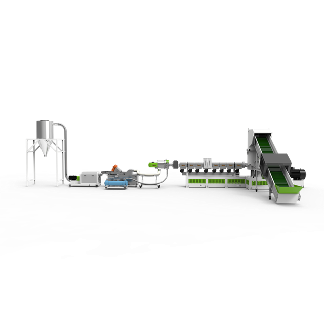
Connecting vacuum receivers to extruders requires technical precision and a deep understanding of material flow rates. Silos and volumetric or gravimetric feeders must sync perfectly with the conveying cycles. Conveying capacity must align with the output rates of your chosen plastic pelletizing machine manufacturer. Mismatched capacities create immediate bottlenecks on the production floor.
If the extruder demands more material than the vacuum system can deliver, production starves, leading to inconsistent melt pressure and poor product quality. If the vacuum system delivers too much, receiver hoppers overfill, leading to filter blinding and system shutdowns. Level sensors in the destination hoppers must communicate seamlessly with the vacuum control panel to initiate and terminate conveying cycles based on real-time demand. Proper venting of the destination hoppers is also required to ensure displaced air does not interfere with the gravity feeding of pellets into the extruder throat.
Vacuum systems operate within specific physical boundaries dictated by atmospheric pressure. They are optimal for distances under 300 feet and handle low-to-medium throughputs best. Because the maximum theoretical driving force is limited to roughly 14.7 psi (a perfect vacuum), you cannot pull more vacuum than absolute zero. In practical industrial applications, systems rarely operate beyond 10 to 12 Hg of vacuum.
Energy efficiency varies among vacuum pumps. Regenerative blowers are cost-effective and suitable for short distances and highly porous materials. Positive displacement (Roots-type) blowers offer a steeper performance curve, maintaining airflow against higher resistance, making them better for longer runs or denser materials. Evaluate pump efficiency against the required conveying distance and throughput. Pushing material over very long distances or at massive bulk rates remains the domain of positive pressure systems, which can utilize compressors to generate 40 psi or more of driving force.
Strict maintenance schedules keep vacuum systems blockage-free. Focus heavily on air filter integrity and the condition of the rotary valve clearances. Perform regular regulator checks along the compressed air supply lines that feed the reverse-pulse cleaning system. If the compressed air pressure drops, the filter will not clean properly, leading to blinding and loss of conveying velocity.
Adequate negative pressure must exist for every conveying cycle. Monitor pressure and vacuum restore times closely. Complete line clearance between runs depends on full pressure recovery. If the vacuum pump fails to reach the required operating pressure before the next feed cycle begins, the initial air velocity will be too low to suspend the pellets, causing immediate settling. Check for vacuum leaks at all pipe joints, flexible hose connections, and receiver discharge valves. Even a small leak can significantly degrade system performance and increase the risk of choking.
Evaluate your plastic pelletizing machine supplier carefully before finalizing equipment purchases. Look for documented material testing facilities where they can run your specific polymer grade through a pilot conveying system. Demand guarantees on conveying rates based on your actual bulk density and particle shape, not just theoretical calculations.
Ensure they possess expertise in handling your specific polymer grade, especially if it is prone to angel hair formation or excessive dusting. Full-system warranties offer significant value and peace of mind. Sourcing the pelletizer and the pneumatic conveying equipment from a single vendor or a tightly integrated partnership reduces integration risks. A unified control architecture simplifies troubleshooting, reduces operator training time, and ensures all components communicate seamlessly without custom programming or complex handshakes between different PLC brands.
No pneumatic system is entirely immune to blockages, but a properly engineered vacuum conveying setup offers superior fail-safes. It provides gentler handling, complete cleanout capabilities, and automated choke prevention that protects plastic pellets effectively. Facilities prioritizing product integrity and operating within moderate distances will find vacuum systems highly reliable, especially when suffering from chronic positive-pressure blockages.
A: Blockages are typically caused by a drop in conveying air velocity, excessive feed rates, moisture in the air lines, or the buildup of friction-melted materials and fines at pipe bends.
A: Vacuum systems pull material using negative pressure, which prevents severe material compaction and allows for automated feed shut-offs if vacuum levels spike, whereas positive pressure pushes material and can pack it tightly into a solid plug.
A: Yes. Increasing the pipe diameter along the conveying route accommodates air expansion, maintains a consistent, gentle velocity, and reduces the friction that leads to blockages.
A: The filter separates the plastic pellets and dust from the conveying air. If the filter blinds (clogs), the system loses vacuum pressure, velocity drops, and the line will inevitably choke.
A: Vacuum restore time is the period required for the system to recover sufficient negative pressure between conveying cycles. If the system does not fully recover its vacuum potential, the next cycle will start with inadequate velocity, increasing the risk of material settling and plugging.
A: Evaluate manufacturers based on their ability to provide comprehensive material flow testing, their experience with your specific polymer's bulk density, and their capability to seamlessly integrate extrusion with automated vacuum conveying controls.


