
- All
- Product Name
- Product Keyword
- Product Model
- Product Summary
- Product Description
- Multi Field Search
 English

Views: 0 Author: Site Editor Publish Time: 2026-07-24 Origin: Site


Erratic pellet flow acts as a hidden margin-killer in polymer processing. It directly causes inconsistent extruder feeding, material degradation, and costly line downtime. Traditional positive pressure systems often introduce excess heat and friction into the conveying line. This thermal and mechanical stress leads to the creation of "angel hair," fines, and unstable bulk density at the receiver end. Plant engineers must solve these issues to maintain product quality and operational efficiency.
To protect material integrity and ensure continuous throughput, technical evaluators increasingly specify vacuum conveying. This method utilizes negative pressure to pull materials gently through the line. This guide examines the mechanics, engineering requirements, and implementation realities of using a vacuum-based plastic pellet conveying system to stabilize pellet transfer. You will learn how to configure pipework, select vacuum sources, and mitigate common pneumatic transfer risks.
Vacuum systems pull material through an enclosed pipe network to a collecting vessel using negative pressure. Overpressure systems push material using compressed air. This fundamental difference dictates how heat interacts with your polymer. Positive pressure blowers generate significant heat during air compression. If this hot air enters the transport pipeline, it risks melting heat-sensitive plastic pellets. When handling materials like PET or specialized elastomers, even a slight temperature increase alters the surface friction of the pellet, causing it to smear against the pipe walls.
Vacuum conveying offers a distinct thermal advantage. Engineers place the vacuum source at the receiving end of the line. The heat generated by the blower exhausts into the atmosphere rather than entering the material stream. This configuration protects fragile resins from premature melting and maintains stable bulk density throughout the transfer process. By keeping the conveying air at ambient temperature, the physical properties of the pellets remain unchanged from the silo to the extruder throat. This thermal isolation proves highly effective when transferring materials over long distances where friction already contributes to temperature rise.
Selecting the correct vacuum generator ensures consistent airflow and prevents line blockages. The choice depends heavily on your conveying distance, material volume, and the specific gravity of the resin. Plant managers must evaluate the performance curves of different blowers to match their facility's layout.
Air velocity, line pressure, and pellet transfer speed share a complex relationship. As air moves through a vacuum line, it expands. This expansion causes the pneumatic conveying air pressure to drop along the line. Consequently, pellet transfer speed increases as the system air pressure drops. Unchecked velocity leads to severe material degradation. If pellets travel too fast, they shatter upon impact with elbows or the receiver wall.
Conveying distance, vertical lifts, and elbows contribute to cumulative pressure drops. The system must adapt to these physical changes to prevent material dropout or excessive velocity at the discharge terminal. Engineers calculate these variables to maintain a stable, laminar flow from the source to the receiver. A properly designed system keeps the air velocity just above the saltation velocity—the minimum speed required to keep the pellets suspended in the air stream. Dropping below this speed causes the line to plug, requiring manual cleanout and causing significant downtime.
To manage these dynamics, technicians monitor vacuum gauges installed at the receiver and the blower. Sudden spikes in vacuum pressure indicate a developing plug or a blinded filter. Gradual increases over weeks suggest material buildup inside the pipework. Regular monitoring allows maintenance teams to address flow restrictions before they halt production.
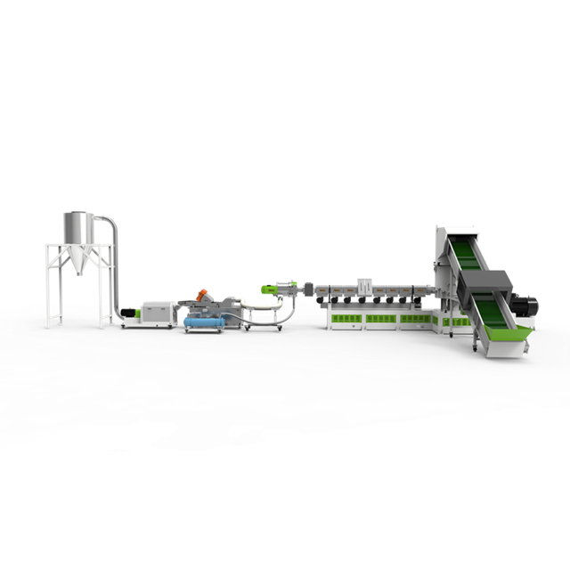
High-velocity collisions with pipe walls generate friction. This friction creates dust, fines, and long polymeric strings known as angel hair. These byproducts clog filters, choke airflow, and severely degrade final product quality. Managing this requires strict control over transfer speeds. When angel hair forms, it wraps around rotary valves and blocks material flow in the hopper, leading to starved extruders.
Controlled vacuum velocity minimizes particulate creation. Engineers calculate specific air-to-cloth ratios in receivers to reduce surface melting. Keeping the pellet speed below the degradation threshold prevents the formation of angel hair and preserves the structural integrity of the resin. Installing inline fines separators or dedusting units before the material enters the processing machine provides an additional layer of protection, ensuring only clean pellets reach the screw.
Pressure drop mitigation relies heavily on pipework geometry. Engineers shape the pipework to manage expanding air. They increase the pipe bore by a fixed diameter at calculated intervals. This stepped pipeline design maintains constant velocity and prevents pellets from accelerating to damaging speeds. For example, a line might start with a 3-inch diameter at the source and step up to a 4-inch diameter halfway to the receiver.
Routing choices also impact flow stability. Long-radius sweeps and specialized deflection elbows reduce impact angles. Internal pipe treatments, such as shot-peening, create a micro-textured surface that disrupts the formation of angel hair. These geometric and surface modifications maintain laminar flow across the entire transfer route. Avoid using standard 90-degree plumbing elbows, as the sharp turn causes pellets to slam into the wall, shattering fragile materials and creating excessive dust.
| Pipe Component | Standard Design Impact | Optimized Design Impact |
|---|---|---|
| Elbows | Sharp 90-degree bends cause high impact, shattering pellets and creating fines. | Long-radius sweeps or deflection elbows gently redirect flow, minimizing impact damage. |
| Internal Surface | Smooth stainless steel promotes sliding friction, leading to angel hair in soft resins. | Shot-peened or dimpled surfaces create tumbling action, preventing frictional melting. |
| Diameter | Constant diameter causes air expansion to accelerate pellets to dangerous speeds. | Stepped diameters accommodate air expansion, keeping pellet velocity constant and safe. |
Clogged receiver filters choke airflow immediately. This causes rapid pressure spikes and destabilizes pellet transfer rates. The configuration of the vacuum receiver and its inlet geometry directly affects how efficiently pellets separate from the conveying air stream. Tangential inlets force the material into a cyclonic motion, allowing heavier pellets to drop out of the air stream naturally before reaching the filter media.
Facilities implement automated compressed air backflow, or pulse-jet cleaning, to continuously purge filters. Robust rotary airlocks or double-flap discharge valves maintain a tight vacuum seal during material discharge. These mechanical solutions prevent pressure leaks and ensure continuous, stable operation. Routine inspection of the discharge valve seals prevents false air from entering the system, which would otherwise reduce the lifting capacity of the vacuum blower.
Selecting the right conveying phase dictates the success of your material handling strategy. Each phase serves distinct polymer types and operational requirements. Dilute phase systems suspend the material in the air stream, requiring higher velocities. Dense phase systems move material in distinct slugs, utilizing high vacuum and low velocity.
Dilute phase works well for standard, non-abrasive, and durable resins like virgin polyethylene. It requires lower capital investment but carries a higher risk of friction. Dense phase is mandatory for fragile, highly filled materials like glass-filled nylon, or highly abrasive compounds. While dense phase requires higher capital expenditure and energy consumption, it maximizes material preservation and extends the lifespan of the pipework by reducing abrasive wear.
Plant engineers must assess footprint requirements for vacuum receivers, collection vessels, and secondary filtration units. Floor space dictates equipment placement and routing complexity. Upgrading a line requires careful spatial planning to avoid disrupting adjacent operations. Overhead routing keeps the floor clear but requires robust support structures to handle the dynamic loads of material moving through the pipes.
Examine integration requirements closely. The vacuum conveying controls must interface seamlessly with upstream equipment provided by your plastic pelletizing machine supplier. Proper integration ensures synchronized operation between pelletizers, classifiers, silos, and the vacuum transfer system. Centralized PLC systems allow operators to monitor fill levels, blower performance, and filter status from a single interface, streamlining troubleshooting and maintenance.
Undersized blowers lead to line plugging and erratic flow. Oversized blowers cause excessive velocity, leading to severe material degradation and energy waste. Both scenarios destroy process stability and increase maintenance demands. An oversized blower will pull material so fast that it destroys the pellets and wears through the elbows in a matter of months.
Demand rigorous pneumatic conveying calculations from vendors. Factor in exact bulk density, maximum conveying distance, number of sweeps, and routing complexity. Accurate sizing guarantees the vacuum source matches the specific aerodynamic requirements of your polymer. Always account for future capacity increases when sizing the blower, utilizing Variable Frequency Drives (VFDs) to dial back the power for current needs while reserving capacity for later expansion.
Masterbatch, regrind, and additives often possess differing bulk densities. During vacuum transit, these materials can separate due to varying aerodynamic properties. This segregation ruins the consistency of the final extruded product, leading to color variations and structural weaknesses in the molded parts.
Utilize specialized receiver designs to combat this issue. Controlled discharge valves and mass-flow hoppers help re-blend materials at the discharge point. These engineered solutions prevent segregation and ensure a homogenous mix enters the extruder throat. Baffle plates inside the receiver can also disrupt the flow, forcing different materials to mix as they drop into the hopper.
Selecting the right equipment provider minimizes long-term operational risks. When evaluating a partner, require access to in-house material testing facilities. Prove flow stability with your specific resin before finalizing the purchase. Testing reveals how your exact blend behaves under vacuum, highlighting potential issues with fines generation or segregation.
Evaluate the vendor's ability to provide transparent performance guarantees. Request comprehensive system documentation, including detailed pressure drop calculations and pipe routing schematics. Ensure they offer responsive post-installation support to address any unforeseen flow dynamics. A reliable vendor will assist with commissioning, ensuring the system operates at the calculated velocities and providing training for your maintenance staff.
A: Vacuum conveying systems typically handle distances up to 300 feet (90 meters) effectively. Beyond this range, the required vacuum levels become difficult to maintain, and pressure drops increase significantly. For longer distances, engineers usually recommend transitioning to positive pressure systems or utilizing sequential vacuum relay stations.
A: Vacuum systems place the blower at the receiving end of the line. The heat generated by compressing air exhausts outward rather than entering the conveying pipe. This configuration keeps the transport air at ambient temperature, preventing heat-sensitive plastic pellets from melting or degrading during transit.
A: As air moves through a vacuum pipeline, it expands due to the continuous drop in pressure. This volumetric expansion forces the air to move faster to maintain mass flow. Consequently, the pellets suspended in the air stream accelerate, requiring stepped pipework to control the velocity.
A: Yes, vacuum conveyors handle mixed materials, but differing bulk densities can cause segregation during transit. To prevent this, systems handling virgin and regrind blends must utilize mass-flow hoppers and specialized receiver geometries to ensure the materials remain properly mixed upon discharge.
A: Pressure drops occur due to friction between the air, the pellets, and the internal pipe walls. Vertical lifts, elbows, long conveying distances, and clogged receiver filters significantly increase resistance. Engineers must calculate these factors to size the vacuum blower correctly.
A: Choose a PD blower for long distances requiring high vacuum and steady airflow. Select a regenerative blower for short runs with high volume and low vacuum needs. Use a Venturi unit for compact, low-maintenance, point-to-point transfers where compressed air is readily available.
A: Pipe bore diameter dictates air velocity. If the diameter remains constant over a long run, expanding air causes velocity to spike, damaging pellets. Stepping up the bore diameter at calculated intervals allows the air to expand without increasing speed, maintaining stable, laminar flow.


