
- All
- Product Name
- Product Keyword
- Product Model
- Product Summary
- Product Description
- Multi Field Search
 English

Views: 0 Author: Site Editor Publish Time: 2026-07-22 Origin: Site


Establishing a recycling facility requires significant capital expenditure, and the critical window between equipment delivery and operational readiness dictates project success. Poor site execution directly causes delayed commissioning, severe safety hazards, and compromised material throughput. Inadequate foundation leveling, utility miscalculations, and poor spatial planning can turn a high-end machinery investment into a logistical nightmare. Facility operators must bridge the gap between factory testing and real-world production through strict engineering controls.
A phased, engineering-led approach to site preparation, plastic recycling machine installation, and commissioning minimizes downtime. This systematic methodology ensures regulatory compliance, aligns mechanical and electrical systems to exact tolerances, and accelerates the timeline to reach full operational capacity. Executing these steps correctly transforms delivered steel into a synchronized, high-yield production asset, ensuring your facility hits target throughput on schedule.
Heavy recycling machinery generates immense dynamic forces. The civil engineering requirements for dynamic load-bearing concrete foundations must account for continuous vibration, especially under heavy crushers, shredders, and granulators. Insufficient foundation mass or improper concrete curing leads to vibration-induced wear, micro-fractures in machine frames, and premature bearing failure. Facilities must utilize reinforced concrete pads isolated from the main floor slab using vibration-dampening materials to absorb shock loads during aggressive shredding cycles. We typically specify 4000 PSI concrete with a full 28-day cure time before anchoring heavy rotating equipment.
Spatial planning dictates operational efficiency. Facility layouts must define the exact footprint of the machinery while securing ample clearance for material handling equipment like forklifts, overhead cranes, and front-end loaders. Mandatory maintenance access zones must be marked around screens, die heads, and pump stations to allow technicians to extract heavy components without dismantling adjacent equipment. You need at least two meters of clearance around the extruder barrel for screw extraction.
Facility scalability requires forward-thinking layout designs. Infrastructure must support modular capacity upgrades. A plant initially designed to process 500 kg/h should have the spatial and utility framework to seamlessly scale to 2,000 kg/h. Reserving floor space for additional friction washers or parallel extrusion lines prevents costly facility modifications during future expansion phases. Plan your trench drains and cable trays for the final phase, not just phase one.
Electrical infrastructure forms the backbone of the facility. High-torque shredders and extruders demand massive startup currents. Facilities require dedicated step-down transformers, industrial-grade switchgears, and robust grounding systems to handle high-amperage startup loads safely. Cable trenches must be mapped early to separate high-voltage power lines from low-voltage communication cables, preventing electromagnetic interference. Running 480V motor leads next to 24V DC sensor wires will cause erratic PLC behavior.
Water management dictates the sustainability and operating limits of the plant. You must specify water supply lines and closed-loop wastewater treatment integration points early in the design phase. A high-capacity plastic washing line relies on continuous water circulation. Integrating filtration systems and sludge removal directly into the utility map prevents bottlenecks and ensures compliance with discharge regulations. Pipe sizing must account for friction loss over long runs to maintain required GPM at the friction washers.
Compressed air systems power critical sorting and automation components. Pneumatic sorting platforms, optical sorters, and automated diverter valves require clean, dry, and stable compressed air. Utility maps must detail compressor locations, receiver tank capacities, and air dryer specifications to guarantee the precise actuation of high-speed sorting ejectors. Moisture in the air lines will destroy pneumatic valve seals within weeks.
| Utility Type | Requirement Focus | Field Execution Standard |
|---|---|---|
| Electrical | High-amperage startup, EMI prevention | Separate high/low voltage trenches, dedicated grounding rods |
| Water | Continuous flow, sludge management | Oversized PVC/Stainless piping, integrated bypass valves |
| Pneumatics | Clean, dry air for optical sorters | Refrigerated air dryers, localized receiver tanks |
Local environmental regulations must integrate directly into the initial site layout. Compliance with Extended Producer Responsibility (EPR) mandates, environmental protection agency licensing, and waste-to-resource frameworks dictates specific facility designs. Ignoring these parameters during the planning phase results in operational blockades and severe legal penalties. You must secure discharge permits before pouring the first yard of concrete.
On-site Effluent Treatment Plants (ETP) require precise layout mapping to manage wash water discharge legally. The ETP must be sized to handle the maximum hourly wastewater output, incorporating chemical dosing stations, dissolved air flotation (DAF) units, and sludge presses. Proper spatial allocation ensures the ETP operates efficiently without encroaching on the main production floor. Keep the chemical storage areas bunded and separate from high-traffic forklift zones.
Safety compliance extends to physical facility modifications. Layouts must incorporate noise abatement enclosures around high-decibel equipment like granulators. Ventilation systems must be engineered to capture and neutralize volatile organic compounds (VOCs) emitted during the extrusion process. Clear, unobstructed emergency egress routes must be painted and maintained across all operational zones.
The raw material intake area determines the efficiency of the entire downstream process. Design and install this zone focusing on heavy-duty bale breakers, automated de-labeling machines, and ergonomic manual or optical sorting platforms. The intake area must handle highly compacted bales without jamming, requiring robust infeed conveyors and aggressive rotor designs. Anchor the bale breaker directly to the reinforced slab to handle the shock loads of frozen or highly compacted bales.
Establish strict protocols for segregating target polymers like PET bottles or HDPE containers while eliminating severe contaminants. PVC, rogue metals, and flexible films cause catastrophic damage to downstream extruders and degrade final pellet quality. Installing overband magnets, eddy current separators, and NIR (Near Infrared) optical sorters in this initial zone protects the core machinery. Calibrate the optical sorters using actual samples from your local waste stream, not generic factory profiles.
Upon arrival, all equipment requires rigorous inspection against the detailed packing list and the Factory Acceptance Test (FAT) reports. Verify that no components suffered transit damage, focusing on sensitive electrical panels, exposed motor shafts, and delicate sensor arrays. Document any discrepancies immediately to facilitate rapid replacement parts dispatch. Take photos of every crate before opening.
Safe rigging and lifting procedures protect both personnel and the machinery. Utilize certified overhead cranes or heavy-duty industrial forklifts rated well above the equipment's gross weight. Rigging teams must use designated lifting eyes and spreader bars to prevent structural distortion of machine frames. Improper lifting techniques can permanently warp extruder barrels or misalign shredder cutting chambers.
Anchoring base plates initiates the mechanical assembly. Equipment must be leveled using precision lasers or machinist levels before applying high-strength epoxy grouting. Proper grouting fills voids between the machine base and the concrete foundation, ensuring uniform load distribution and preventing localized stress fractures during heavy operation. Do not tighten anchor bolts to final torque until the grout has fully cured.
Aligning drive shafts, couplings, and belts to exact manufacturer tolerances prevents premature bearing failure and excessive energy consumption. Misaligned couplings generate severe vibration and heat, rapidly destroying seals and bearings. Technicians must utilize dial indicators or laser alignment tools to ensure perfect concentricity between motors and driven shafts. Soft foot conditions under motor mounts must be shimmed out before final alignment.
Routing power and control cables demands strict organization. Cables must run through designated, separated trays to minimize electromagnetic interference (EMI) that can disrupt sensitive sensor signals. High-voltage motor cables and low-voltage PLC communication lines must never share the same conduit. Use shielded cables for all VFD and analog sensor runs, grounding the shield at one end only to prevent ground loops.
The termination process for Programmable Logic Controllers (PLCs), sensors, and Variable Frequency Drives (VFDs) requires meticulous attention to the electrical schematics. Technicians must ensure all safety interlocks, emergency stops, and thermal sensors are hardwired correctly. A single bypassed safety relay compromises the entire facility's operational integrity. Ring out every wire point-to-point before applying control power.
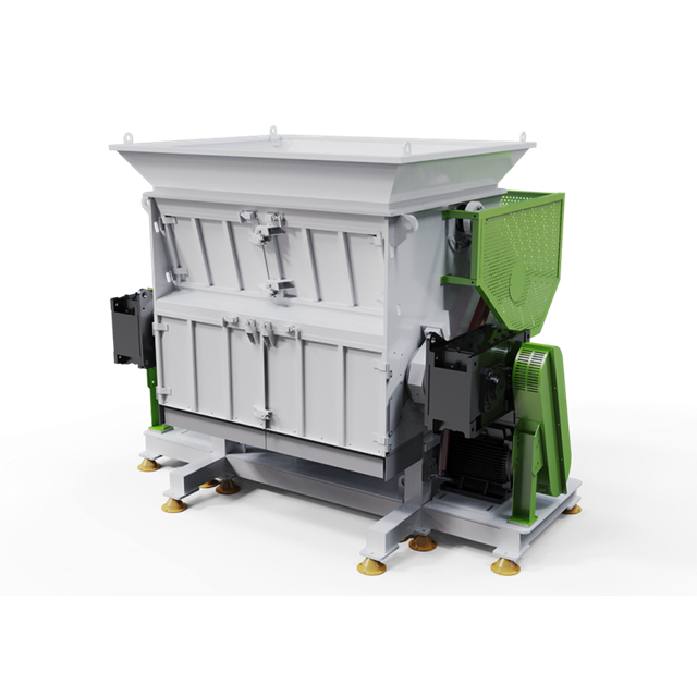
Friction washers, sink-float tanks, and thermal dryers require specific installation protocols. Friction washers must be anchored securely to withstand high-RPM dynamic loads. Sink-float tanks require precise leveling to ensure uniform water overflow and accurate density separation of polymers. Thermal dryers demand proper exhaust ducting to expel moisture-laden air outside the facility, preventing internal condensation. Pitch the exhaust ducts slightly downward toward the outside to prevent condensation from running back into the dryer housing.
Water circulation pumps, filtration screens, and automated sludge removal systems demand critical alignment. Piping must be routed to minimize sharp bends, reducing pressure drops and preventing pump cavitation. Continuous flow is mandatory; any interruption in the water supply degrades the washing efficiency and allows contaminants to pass into the extrusion phase. Install pressure gauges on both sides of the filtration screens to monitor blinding.
The setup for extruders involves assembling complex thermal and mechanical components. Technicians must install heating bands securely, ensuring optimal surface contact for efficient heat transfer. Melt pressure sensors and thermocouples must be calibrated to monitor polymer behavior accurately. Degassing vents require connection to high-capacity vacuum pumps to extract volatile gases and residual moisture from the polymer melt. Apply anti-seize compound to all sensor threads to prevent galling at high temperatures.
Integrating the die-face cutter or strand pelletizer requires extreme precision. The cutting blades must align perfectly with the die plate to ensure uniform pellet geometry and prevent smearing. A properly calibrated plastic pelletizing system produces consistent, high-bulk-density pellets that meet strict industry specifications. Adjust the blade pressure dynamically as the die plate reaches operating temperature to account for thermal expansion.
Mechanically and electrically linking infeed conveyors, shredders, and discharge silos creates a cohesive production line. Conveyor transition points must be sealed to prevent material spillage. Discharge silos require level sensors to prevent overfilling and integrate with automated bagging stations. Use heavy-duty skirting rubber at all transfer points to contain dust and fines.
Programming Variable Frequency Drives (VFDs) ensures synchronized material flow across the entire facility. VFDs allow operators to fine-tune conveyor speeds, matching the intake rate to the extruder's processing capacity. Proper synchronization prevents material starvation at the extruder throat and eliminates bottlenecks in the washing tanks. Set up PID loops in the PLC to automatically adjust infeed conveyor speed based on shredder motor amperage.
Before applying any power, technicians must execute mandatory mechanical and electrical checks. This includes the verification of all mechanical fasteners to specified torque settings, confirmation of gearbox lubrication levels, and point-to-point electrical continuity testing. These audits catch installation errors before they cause catastrophic equipment failure. Physically check every gearbox drain plug; they are often left loose during shipping.
Testing safety systems is the final step before motor activation. Technicians must manually trigger all emergency stops (E-stops), verify the engagement of safety guards, and test thermal overloads. No motor should be energized until the entire safety circuit is proven fully operational. Document the successful test of every single E-stop button on the line.
| System Category | Audit Action | Acceptance Criteria |
|---|---|---|
| Mechanical | Check foundation bolts and grouting | Torqued to spec; zero voids in grout |
| Electrical | Point-to-point continuity test | Zero faults; correct phase alignment |
| Lubrication | Verify gearbox and bearing oil levels | Filled to sight-glass center with correct viscosity |
| Safety | Trigger all E-stops and interlocks | Immediate system halt; alarms activate |
Dry commissioning begins by bumping motors to verify correct rotational direction. Reversing a high-speed shredder or extruder screw can cause immediate, irreversible damage to the cutting tools and gearboxes. Have a spotter at the motor fan cover to confirm rotation direction instantly.
Once rotation is confirmed, technicians run the entire line empty. This no-load testing phase allows engineers to monitor for abnormal vibrations, acoustic anomalies, and baseline temperature rises in bearings. Any excessive heat or vibration indicates mechanical misalignment that must be corrected before introducing material. Use a thermal imaging camera to scan all bearing housings after 30 minutes of dry running.
Wet commissioning introduces water into the system. Technicians test for pipe leaks, verify pump pressure metrics, and evaluate thermal dryer efficiency. The water filtration and sludge removal systems are tested to ensure they can maintain clear water circulation under continuous operation. Balance the water flow valves to ensure the sink-float tanks maintain a steady overflow without turbulence.
Material load testing involves the phased introduction of plastic scrap. Operators feed the system at 25%, then 50%, and finally 100% capacity. During these phases, engineers evaluate shredder torque response, extruder melt pressure stability, and overall system throughput. This data is compared against the guaranteed performance metrics to validate the installation. Monitor the melt temperature closely as you increase feed rates to prevent polymer degradation.
Top-tier manufacturers assist heavily in the pre-installation phase. They provide precise utility load calculations, review civil engineering drawings, and contribute to comprehensive feasibility studies. This engineering support ensures the facility is designed correctly from day one, preventing costly retrofits during the installation phase. Demand a detailed utility consumption matrix before finalizing your facility design.
Factory Acceptance Testing (FAT) provides pre-shipment validation at the manufacturer's facility. Site Acceptance Testing (SAT) provides post-installation validation at the buyer's facility. A manufacturer's presence during SAT is a critical evaluation dimension. The SAT proves that the equipment performs to specification under actual site conditions, utilizing local utilities and real-world feedstock. Never sign off on final payment until the SAT is successfully completed on your floor.
Operator and maintenance training programs conducted by the manufacturer's commissioning engineers are necessary for long-term success. Your staff must understand how to clear jams, replace screens, and troubleshoot PLC alarms safely. Hands-on training during the load testing phase is the most effective way to transfer knowledge.
Required handover documentation includes as-built electrical schematics, PLC source code, detailed maintenance schedules, and comprehensive spare parts lists. Without these documents, independent troubleshooting and routine maintenance become nearly impossible. Ensure the PLC code is unlocked and fully commented in your local language.
Evaluating a vendor's post-commissioning support ensures operational longevity. A reliable plastic washing line manufacturer offers remote diagnostics capabilities, maintains a robust local spare parts inventory, and provides Service Level Agreements (SLAs) for rapid downtime mitigation. Fast access to replacement shredder blades and extruder screws keeps the facility profitable. Verify their remote login security protocols before connecting the machine network to the internet.
A: A complete installation typically takes 4 to 8 weeks from equipment delivery to SAT completion. This includes unloading, rigging, mechanical assembly, electrical integration, and phased commissioning. Complex, high-capacity lines with extensive wastewater treatment integration may require up to 12 weeks.
A: Heavy machinery requires reinforced concrete foundations, often 300mm to 500mm deep, depending on the dynamic load. High-vibration equipment like shredders requires vibration isolation pads and high-strength epoxy grouting to prevent structural fatigue and maintain alignment.
A: SAT accounts for variables introduced by shipping, local utility fluctuations, and actual facility conditions. It validates that the machinery achieves guaranteed throughput and quality metrics using your specific feedstock and operators, which FAT cannot fully replicate.
A: Standard clearance metrics dictate at least 1.5 to 2 meters of unobstructed space around major components. This allows safe access for forklifts to remove heavy motors, replace extruder screws, and extract filtration screens without dismantling adjacent machinery.
A: The most frequent delays stem from utility mismatches, incomplete civil foundation work, missing safety compliance certifications, and poor synchronization between third-party material handling conveyors and the main processing line.
A: Most top-tier manufacturers provide supervisory commissioning services, sending lead engineers to direct your local contractors. Turnkey installations, where the manufacturer supplies all rigging and assembly labor, are available but typically require separate, specialized contracts.


