
- All
- Product Name
- Product Keyword
- Product Model
- Product Summary
- Product Description
- Multi Field Search
 English

Views: 0 Author: Site Editor Publish Time: 2026-08-05 Origin: Site


The profitability of a plastic recycling facility is won or lost in the initial facility design phase, not just in the equipment purchased. Operators often focus heavily on individual machine specifications while neglecting the spatial and logistical framework connecting them. Fragmented planning leads to spatial bottlenecks, excessive energy consumption, cross-contamination, and inefficient material handling between processing stages. To build a resilient operation, facility engineers must adopt a systematic framework for designing a continuous, scalable plastic recycling plant layout. A well-engineered floor plan logically integrates sorting, washing, and extrusion systems while mitigating daily operational risks. By mapping out material flow, utility drops, and maintenance access corridors from day one, plant managers ensure maximum uptime and consistent end-product quality.
A successful facility design relies on hard mathematical realities rather than rough estimates. The primary constraint always comes down to balancing targeted throughput against available footprint. Processing 10,000 tons per year requires a vastly different spatial strategy than a 50,000-ton mega-facility. You must calculate the exact square footage required not just for active processing machinery, but for raw material staging, intermediate buffering, and finished goods storage. We always start by mapping the physical dimensions of the largest components and working backward to the smaller auxiliary units.
Feedstock variability heavily dictates layout complexity. A facility processing post-consumer PET bottles from municipal Material Recovery Facilities (MRFs) faces high contamination levels. This requires extensive sorting and aggressive friction washing zones. Conversely, a plant handling highly consistent post-industrial LDPE film waste streams utilizes a shorter, more streamlined processing line. The physical length of your processing line expands directly in proportion to the contamination level of your input material. You must account for these variables early in the drafting phase.
Layout design must center around strict feed specifications. Whether you prepare material for mechanical pelletizing or advanced pyrolysis operations, the system must reliably hit rigorous industry thresholds for moisture content, PVC limits, and metal contamination. If your layout lacks the necessary footprint for adequate thermal drying or secondary eddy current separators, you fail to meet these specifications. We see many plants struggle because they underestimated the space needed for secondary sorting.
Map your layout backward from your desired output specifications. Producing food-grade rPET flakes demands cleanroom-style segregation and advanced optical sorting stages. Manufacturing extrusion-ready compound pellets or raw nurdles for plastic manufacturers requires dedicated space for melt filtration and homogenization silos. The end-product determines the necessity of advanced decontamination stages. You cannot retrofit a cleanroom into a dirty facility without massive disruption.
| Feedstock Type | Expected Contamination | Layout Complexity | Primary Space Requirement |
|---|---|---|---|
| Post-Consumer PET Bottles | High (Labels, Adhesives, Organics) | High | Extensive sorting arrays, long hot wash tanks |
| Post-Industrial LDPE Film | Low (Dust, Minor debris) | Low to Medium | Large buffer silos, shredding zones |
| Mixed Rigid Plastics (HDPE/PP) | Medium (Metals, Mixed polymers) | Medium | Sink-float density separation tanks |
| Agricultural Films | Very High (Soil, Sand, Biomass) | Very High | Heavy-duty trommels, aggressive friction washers |
To ensure your layout meets all success criteria, follow these specific planning steps:
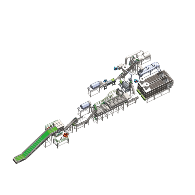
The intake zone sets the operational tempo for the entire plant. Heavy transport trucks require massive turning radii, reinforced concrete weighing bridges, and designated unloading bays. You must design distinct flow paths for incoming waste to prevent traffic jams between regional municipal haulers dropping off bales and industrial suppliers delivering loose scrap. A congested yard immediately throttles your processing capacity.
Bale storage and quality control (QC) testing zones demand strict physical segregation. Raw, contaminated feedstock must never cross paths with processed materials. Integrate a dedicated QC area right at the unloading dock for testing incoming bale moisture and polymer purity. If a load fails to meet feed specifications, quarantine it immediately without disrupting the main processing flow. We use painted floor lines and physical barriers to enforce these zones.
The mechanical size and air separation sequence requires significant vertical and horizontal clearance. Initial size separation utilizes trommels or disc screens to filter out undersized debris like glass shards and dirt. Following this, air classification systems, such as wind sifters or zig-zag air separators, remove light fractions like paper, labels, and film foils early in the process. Allocating sufficient footprint for these early separation stages prevents downstream equipment wear.
Automated sorting infrastructure demands precise structural planning. Ballistic separators and near-infrared (NIR) optical sorters require high vertical clearance, heavy-duty mezzanine structures, and vibration-isolated mounting points. While manual sorting cabins require climate control and ergonomic spacing for workers, fully automated multi-sensor optical sorting arrays require extensive data cabling and compressed air lines routed directly to the sorting blocks. You must plan these utility routes meticulously.
Shredding and size reduction zones generate intense noise, heavy vibration, and airborne particulates. Primary shredders and wet or dry granulators must sit on isolated concrete pads. Implement layout mitigation strategies including acoustic enclosures, heavy vibration dampeners, and centralized dust extraction systems to maintain a safe and compliant working environment. We always isolate the shredder foundation from the main building slab to prevent structural damage.
Transitioning from dry sorting to wet processing requires a fundamental shift in facility engineering. Wet granulation and friction washing stages involve high-speed machinery operating in punishing environments. The physical layout must accommodate continuous water circulation piping, insulated steam heating lines for hot wash tanks, and safely segregated chemical dosing stations for caustic soda or detergents. Leaks will happen, so floor drainage must be robust and properly sloped.
Sink-float density separation requires substantial linear space. These tanks separate polymers by specific gravity, such as floating PE/PP caps away from sinking PET flakes. Standard tank lengths work for moderately clean streams, but highly contaminated inputs demand extended tanks or dual-stage separation layouts. You must ensure adequate aisle space alongside these tanks for operators to monitor the skimming mechanisms and clear blockages safely.
Thermal drying and moisture control form the bridge between washing and extrusion. Mechanical dewatering centrifuges remove bulk water, but thermal drying cyclones are necessary to achieve the strict sub-1% moisture threshold required before extrusion. Excess moisture causes severe polymer degradation and foaming in the extruder. The layout must allow for insulated hot air ducting and adequate exhaust ventilation to manage the massive heat load generated here.
Partnering with a reliable plastic washing line manufacturer ensures you get the right equipment for your specific footprint. Evaluate vendors based on their ability to provide modular layouts that fit your building constraints. Demand transparent utility consumption metrics for water and power. Prioritize manufacturers who offer integrated, pre-tested wastewater filtration modules that connect seamlessly to the main washing circuit.
Material buffering and feeding systems act as the shock absorbers of your facility. You cannot feed flakes directly from a plastic washing line into an extruder without a buffer. Silo storage, gravimetric feeders, and buffer silos ensure a consistent, uninterrupted melt-feed rate. If the washing line pauses for a screen change, the buffer silo keeps the extruder running, preventing downtime and material degradation.
Melt filtration and degassing sections of the extruder require specific spatial planning. Single or double-vented extruders need overhead clearance for vacuum pump integration and exhaust piping. Continuous laser filters or dual-piston screen changers filter out residual micro-impurities like aluminum or paper dust. These units require lateral space for operators to safely perform screen swaps while the machine is hot. Do not cramp the extrusion zone.
Selecting the right plastic pelletizing system dictates the footprint of your finishing zone. Strand pelletizing requires significant linear space for long water cooling baths and air knives before the strand cutters. It is easier to monitor visually but consumes more floor space. Conversely, underwater or water-ring pelletizing systems offer a highly compact footprint. They are fully automated and ideal for producing uniform pellets, though they require space for precise temperature control loops and water filtration skids.
The final stages involve cooling, classifying, and storage. Vibration classifiers sort out oversized or undersized pellets, ensuring product uniformity. Pneumatic conveying lines then transport the approved pellets to large storage silos. Finally, automated bagging and packaging stations require space for forklift maneuverability, pallet wrapping, and staging before final shipment. We recommend a minimum of 20 feet of clearance around the bagging station for safe forklift operation.
Closed-loop water management is the lifeblood of wet processing. The wastewater treatment plant (WWTP) must integrate into the primary layout from the beginning, never treated as an afterthought. Detail the gravity-fed trenches and pumped flow lines routing dirty water from the washing stages to flocculation tanks, dissolved air flotation (DAF) units, and sand filters before recirculating clean water back to the line. Proper trenching prevents factory floor flooding.
Power distribution and energy efficiency dictate where heavy machinery can sit. Shredders and extruders draw massive electrical loads. Sub-stations, transformers, and motor control centers (MCCs) must sit as close to these high-draw machines as safely possible. Minimizing high-voltage cable runs reduces line losses, lowers installation costs, and improves overall electrical efficiency. We always mount MCCs on raised platforms to protect them from potential water damage.
A centralized automation and SCADA control room serves as the brain of the facility. This room should be elevated, providing operators with a direct line-of-sight to washing and pelletizing operations. The layout must include dedicated, shielded cable trays routing data from hundreds of machine sensors back to the control room. This ensures real-time monitoring and rapid fault detection without signal interference from high-voltage power lines.
Material transfer bottlenecks are a common point of failure. Evaluate the operational risks of using mechanical screw conveyors versus pneumatic transport ducting. Screw conveyors are robust for heavy, wet materials but consume floor space and have fixed linear paths. Pneumatic ducting is highly flexible and routes material overhead, saving floor space, but is only suitable for dry, lightweight flakes or pellets. Choose the right transfer method for each specific stage.
Modern facilities must often accommodate the co-existence of mechanical and advanced recycling preparation. Design a flexible layout capable of splitting sorted feedstock streams. Route premium, high-purity polymers to the mechanical extrusion system, while diverting lower-grade, hard-to-recycle fractions to a dedicated chemical or pyrolysis preparation line. This requires intelligent diverter valves and secondary buffer silos. Planning for this flexibility now saves massive retrofitting costs later.
Compliance, fire safety, and dust extraction require strict adherence to local codes. Detail necessary spatial allocations for overhead fire suppression systems and clear emergency egress routes. ATEX-compliant dust collection zones are mandatory, particularly around shredding, air separation, and thermal drying areas where combustible polymer dust accumulates. Isolate these high-risk zones with fire-rated walls and blast-relief panels to protect your workforce and your investment.
A successful recycling facility layout is a holistic integration of material science, spatial engineering, and utility management. Equipment placement must respect the realities of material flow, maintenance access, and utility distribution. Ignoring these factors during the design phase guarantees operational bottlenecks and inflated processing costs. When selecting equipment partners, prioritize vendors who offer comprehensive 3D layout modeling, transparent utility guarantees, and proven line-to-line mechanical integration.
To move forward effectively, execute the following steps:
A: Space requirements scale with capacity and feedstock. A 10,000-ton/year facility typically requires 30,000 to 50,000 square feet. This accommodates intake bays, bale storage, the mechanical processing line, water treatment skids, and finished pellet silos. Highly contaminated streams require longer washing lines, further increasing the necessary footprint.
A: Without filtration, washing lines consume 10 to 15 cubic meters of water per ton of plastic. Integrating a closed-loop wastewater treatment plant with flocculation and micro-filtration reduces net freshwater makeup to roughly 1 to 2 cubic meters per ton, replacing only what is lost to evaporation and sludge removal.
A: Evaluate vendors based on their ability to provide modular, customizable designs rather than rigid off-the-shelf systems. Demand reference plant visits to see their equipment running similar feedstock. Prioritize integrated water treatment solutions, robust wear-resistant materials, and guaranteed after-sales spare parts availability.
A: Highly contaminated feedstock requires aggressive melt filtration before pelletizing. For clean, consistent streams, underwater pelletizers efficiently produce high-quality, uniform nurdles. If the melt contains residual impurities that cause strand breakage, a water-ring or hot-die face pelletizer is often more reliable than a traditional strand system.
A: A standard commercial facility typically requires between 1.5 to 3 megawatts of installed power. The heaviest draws come from primary shredders, friction washers, thermal dryers, and extruders. Localized power distribution through strategically placed motor control centers is critical to manage these heavy loads efficiently.
A: Mechanical front-end systems are essential for advanced recycling. Pyrolysis reactors require strict feed specifications regarding moisture, size, and PVC content. A mechanical layout utilizes shredding, air classification, and optical sorting to create a clean, homogenized fluff or densified agglomerate that meets precise chemical recycling standards.


