
- All
- Product Name
- Product Keyword
- Product Model
- Product Summary
- Product Description
- Multi Field Search
 English

Views: 0 Author: Site Editor Publish Time: 2026-08-03 Origin: Site


Material backtracking acts as a hidden operational drain that quietly erodes facility profitability. When a facility design forces materials to move against the primary production flow, it introduces unnecessary handling. This drastically increases forklift traffic and degrades overall throughput. Every time a bale of waste or a bin of flakes travels backward through a processing zone, you lose time and increase the risk of cross-contamination.
Retrofitting new equipment into legacy spaces often forces these non-linear material flows. Operators find themselves squeezing modern machinery into outdated footprints, leading to a tangled web of operations. This setup causes cross-contamination between dirty incoming waste and clean processed flakes. It also drives up energy consumption as materials are moved multiple times and creates severe safety hazards due to congested traffic aisles.
A strategically engineered plastic recycling plant layout requires creating a unidirectional, gravity-assisted, or conveyor-optimized flow. Proper spatial planning drives bottom-line profitability, maximizes material recovery rates, and ensures that every square meter of the facility actively contributes to the production cycle.
Moving materials backward against the primary production flow cripples operational efficiency. When operators must transport intermediate materials back through previous processing zones, cycle times inflate. Energy consumption spikes because conveyors run longer or forklifts make redundant trips. Labor costs escalate as workers spend hours merely staging and moving materials rather than operating machinery. A layout that requires constant manual intervention to bridge gaps between machines fails from day one.
The contamination risk in a poorly planned facility destroys product value. When clean, washed flakes cross paths with incoming baled waste, the risk of re-contamination skyrockets. Airborne dust from the shredding zone easily settles on wet flakes if the zones lack physical separation. This cross-contamination degrades the final product quality, leading to rejected batches and downgraded resin values. Maintaining strict physical boundaries between dirty and clean zones guarantees high-grade recyclate production.
Layout bottlenecks and cross-traffic directly impact Material Recovery Rates (MRR). When material flow stops, accidental waste occurs. Spillage during redundant forklift transfers leads to mixed-resin contamination on the facility floor. Reduced overall yield is the inevitable result of a layout that forces materials to wait in staging areas where they can be contaminated or lost. Maximizing MRR requires a seamless transition from one processing stage to the next.
High forklift traffic in congested areas introduces significant safety and maintenance hazards. Blind corners and narrow aisles increase the likelihood of collisions. Furthermore, backtracking complicates maintenance access. When machinery sits too tightly to accommodate convoluted material flows, technicians cannot easily reach components. This extends downtime during routine maintenance and emergency repairs.
Success criteria for layout optimization must be clearly defined before pouring concrete. A successful layout achieves zero crossover points, meaning materials never travel backward. It minimizes material travel distance, reducing the need for mechanical or manual transport. Isolated utility zones ensure that water and power lines do not interfere with material flow. Finally, a clear reject and byproduct routing path ensures that waste materials exit the production line immediately without bottlenecking the main process.
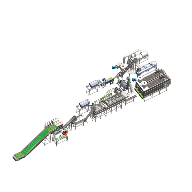
Choosing the right spatial configuration dictates the long-term efficiency of your operation. Facility shape, loading dock locations, and utility access points heavily influence this decision. Each configuration offers distinct advantages and limitations based on the physical constraints of the building.
The straight-line, or linear, layout stands as the gold standard for eliminating backtracking. Materials enter one end of the facility and exit the other as finished pellets. This configuration fits long, narrow facilities perfectly. The primary benefit is absolute zero backtracking and clear visual management. Supervisors can stand at one end of the building and observe the entire production process. However, a purely linear flow requires a specific building footprint and dual loading docks at opposite ends of the structure, which many existing buildings lack.
A U-shaped layout works highly effectively when intake and shipping must occur on the same side of the building. This configuration fits square facilities with limited loading docks. Raw materials enter one side, travel down the facility through the shredding and washing phases, turn, and travel back up the other side through extrusion and bagging. The primary benefit is centralized utility hubs. Water and power route down the center of the "U," servicing both sides of the line efficiently. It also allows for shared logistics zones without crossing the raw and finished processing streams.
L-shaped and multi-level layouts utilize the vertical space within a facility. Gravity-fed systems drastically reduce reliance on mechanical conveyors. Placing silos, optical sorters, or buffer tanks on structural mezzanines saves valuable floor space. An L-shaped layout often helps navigate around immovable building features like support columns or internal offices. Utilizing verticality requires robust structural engineering but pays off by shortening the horizontal travel distance of the material.
| Layout Type | Best Facility Shape | Primary Advantage | Potential Limitation |
|---|---|---|---|
| Straight-Line (Linear) | Long and Narrow | Absolute zero backtracking; clear visual management. | Requires loading docks at both ends of the facility. |
| U-Shaped | Square or Rectangular | Centralized utilities; shared intake/shipping zones. | Requires careful planning at the turn to prevent bottlenecks. |
| L-Shaped / Multi-Level | Irregular or High-Ceiling | Maximizes vertical space; utilizes gravity feeding. | Higher initial structural engineering and installation costs. |
The dry zone sets the pace for the entire facility. Incoming Quality Control (IQC) requires precise spatial planning. You must allocate a dedicated footprint for bale inspection, staging, and de-baling. Manual or semi-automated pre-sorting stations need adequate space for operators to safely remove incompatible caps, closures, and labels before processing begins. If this area is cramped, non-recyclable materials will inevitably slip into the shredders, causing downstream contamination and equipment wear.
Integrating advanced sorting footprints demands structural foresight. AI-powered optical sorters and robotics require specific structural supports and clearances. You must map out the spatial requirements for these machines, including the necessary acceleration conveyors that feed them. Ensure adequate catch-bins and reject-chutes sit directly beneath or adjacent to the sorters. This prevents rejected materials from bottlenecking the primary feed line and allows for easy removal by forklift without crossing the clean material path.
Acoustic and dust isolation in the shredding and granulation area is mandatory. Size reduction generates immense noise and airborne particulates. Isolating this area with acoustic panels and heavy-duty dust-containment barriers prevents airborne contamination from reaching downstream processes. If dust from the dry zone settles on wet flakes in the washing zone, it creates a sludge that degrades the final product. Physical walls or heavy strip curtains must separate the dry zone from the rest of the plant.
The wet zone must follow a strict linear progression to maintain material integrity. A standard plastic washing line involves friction washers, sink-float tanks, and centrifugal dryers. Material must flow sequentially through these stages without ever looping back. Friction washers remove surface dirt, sink-float tanks separate materials by density, and dryers remove moisture. Any interruption or backtracking in this sequence allows contaminants to resettle on the flakes.
Byproduct and wastewater routing requires careful subterranean planning. Design dedicated drainage trenches and municipal water filtration loops directly beneath the washing equipment. This prevents water from pooling on the facility floor, which creates slip hazards and degrades the building foundation. Proper drainage eliminates the need to transport wastewater solids or sludge backward through the clean zone for disposal. Sludge should pump directly to an isolated filtration area.
Strategic intermediate storage placement stabilizes the production flow. Buffer silos should sit between the washing and extrusion phases. These silos absorb throughput variations. If the washing line processes material faster than the extruder can handle it, the silos hold the excess. This prevents material from backing up on the line or requiring manual staging in gaylord boxes. Buffer silos keep the material moving forward and protect it from ambient contamination.
The clean zone is highly sensitive to environmental factors. The plastic pelletizing system must sit physically separated from the washing line's ambient humidity and steam. Excess moisture entering the extruder causes foaming, voids in the pellets, and severe quality degradation. A physical barrier, often a solid wall, should separate the wet zone from the heat zone to maintain strict moisture and temperature control.
Optimizing the feed-in loop eliminates manual handling errors. Align the buffer silos directly with the extruder's feeder using vacuum or pneumatic conveying systems. This direct connection eliminates the need for forklift operators to manually load hoppers. Automated conveying ensures a consistent, metered feed rate into the extruder, which stabilizes melt pressure and improves pellet uniformity.
Post-extrusion logistics must streamline for immediate shipping or storage. Map the flow from the extruder die head to the cooling baths, pelletizers, classifiers, and final bagging stations. Finished goods must move directly to the loading dock or warehouse. Under no circumstances should finished pellets pass near the raw material intake or washing byproduct zones. A dedicated exit path guarantees that the final product remains pristine.
Facility design requires balancing upfront capital expenditure against long-term operational savings. Custom conveyor systems, pneumatic blowers, and automated sorting equipment require significant initial investment. However, these systems eliminate the need for forklift material handling between processing stages. The long-term labor savings, reduction in safety incidents, and elimination of material backtracking justify the higher initial cost. Evaluate these investments based on their ability to maintain a continuous, uninterrupted material flow.
Design for Disassembly (DfD) and maintenance access are frequently overlooked during layout planning. Placing machines too close together to save floor space creates a logistical nightmare. Design the layout to allow modular disassembly of key components. Technicians must be able to pull extruder screws, remove washing trommels, and change shredder blades without halting adjacent production steps or moving other machinery out of the way. Adequate clearance around every machine is non-negotiable.
Operators must weigh scalability against current capacity. Leaving empty floor space for future line expansions, such as adding a second extruder or an additional washing module, ensures the facility can grow with market demand. However, this means operating with a less dense footprint initially. Conversely, optimizing the current footprint for immediate maximum density maximizes current output but makes future upgrades difficult and expensive. A strategic layout plans for future utility tie-ins and expansion zones without compromising current flow efficiency.
Piecemeal integration presents a massive risk in facility design. Buying shredders, washing lines, and extruders from different vendors without a master layout plan guarantees integration failures. Different machines have varying feed heights, throughput capacities, and utility requirements. Forcing mismatched equipment to work together results in custom fabrication on-site, awkward material transitions, and inevitable backtracking as operators try to bridge the gaps.
Leveraging a comprehensive plastic washing line manufacturer mitigates these risks. Involving the primary vendor in the architectural phase provides a distinct technical advantage. A capable manufacturer provides 3D CAD modeling, detailed utility consumption maps, and dynamic flow simulations. They ensure that the structural supports, drainage trenches, and electrical drops align perfectly with the equipment footprint. This holistic approach guarantees that the machinery and the building work together as a single, cohesive system.
Phased installation protocols prevent costly mistakes during facility commissioning. Install equipment sequentially to avoid boxing in machinery. Follow these specific steps during installation:
A: The required floor space varies heavily based on capacity and automation levels. A basic 500kg/h line might require 800 to 1,200 square meters. High-capacity, fully automated lines often need upwards of 3,000 square meters to accommodate proper zone segregation, buffer silos, and safe maintenance clearances.
A: A U-shaped layout prevents contamination by keeping the dirty intake zone and the clean extrusion zone on parallel but physically separated tracks. A central dividing wall or utility corridor usually separates the two sides, ensuring airborne dust or moisture cannot travel from the raw material side to the finished product side.
A: The washing line should sit immediately following the shredding zone but separated by a physical barrier or heavy acoustic curtains. Material should transfer via enclosed conveyors to prevent dust from the shredder from settling into the clean washing tanks.
A: Optical sorters require significant space for the machine, the high-speed acceleration conveyors feeding them, and the multiple reject bunkers beneath them. Allocate at least a 10x5 meter footprint per sorting unit to ensure proper material spread and safe forklift access to the reject bins.
A: Buffer space is typically managed vertically using storage silos rather than floor space. You should install enough silo capacity to hold at least two to four hours of washing line output. This ensures the extruder runs continuously even if the washing line stops for brief maintenance.
A: Pneumatic conveyors transport lightweight flakes through overhead pipes using air pressure. They optimize layouts by moving material vertically and across long distances without taking up floor space. This eliminates the need for forklifts, prevents contamination, and allows for flexible routing around obstacles.


