
- All
- Product Name
- Product Keyword
- Product Model
- Product Summary
- Product Description
- Multi Field Search
 English

Views: 0 Author: Site Editor Publish Time: 2026-07-26 Origin: Site


Poorly specified material handling infrastructure in plastic processing facilities introduces severe operational risks. When plant managers rely on estimates rather than hard data to size vacuum lines and blowers, they invite constant material degradation, vacuum line blockages, and unplanned machine downtime. Transitioning to a centralized material handling model requires precise, facility-specific operational data. Guesswork in capacity planning inevitably leads to either expensive over-engineering or crippling system bottlenecks during peak production cycles.
This article serves as a comprehensive central feeding system design guide for plant managers and engineers. You will learn how to audit your production floors, gather the exact data points required, and structure a request for proposal that ensures an accurate, scalable build.
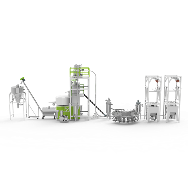
A modern central feeding system operates using a strict one machine, one pipe, sealed circuit methodology. This closed-loop architecture transports raw materials from silos or central drying stations directly to individual processing machines. The entire network relies on precise pneumatic conveying principles to move pellets, powders, or flakes efficiently across the plant floor.
This architecture fails immediately if the initial consumption, pressure drop, and distance data are flawed. Inaccurate data leads to line plugging, vacuum pump cavitation, and material starvation at the machine hopper. A successfully designed centralized feeding system achieves zero cross-contamination, maintains stable vacuum pressure, ensures consistent material moisture levels, minimizes energy consumption, and utilizes a scalable PLC architecture.
When you walk the plant floor, you see the results of bad data. Hoses are taped together, operators manually clear clogged lines, and machines sit idle waiting for resin. Gathering the right data upfront eliminates these issues. You need to measure everything from the bulk density of your specific resin grades to the exact vertical lift from the gaylord to the ceiling trusses.
Engineers must approach this as a fluid dynamics problem. Air is the fluid, and the plastic pellets are the payload. If you do not know the exact weight, shape, and volume of the payload, you cannot calculate the required air velocity. Too slow, and the material falls out of suspension, blocking the pipe. Too fast, and the pellets smash against the elbows, creating dust and angel hair that ruins the final molded product.
The physical shape of your material—whether pellets, powder, flakes, or micro-pellets—and its bulk density directly impact conveying velocity. Bulk density dictates the saltation velocity, which is the minimum air speed required to keep particles suspended in the conveying line. Heavy, dense materials require higher air velocities to prevent them from dropping out of the air stream and clogging the pipes. Abrasive materials will also dictate the need for specialized, wear-resistant pipe materials.
Consider the difference between conveying virgin polycarbonate pellets and conveying light, fluffy regrind. The regrind has a completely different aerodynamic profile. If your system is sized only for the virgin pellets, the regrind will likely cause bridging in the hoppers and erratic flow in the lines. You must document the bulk density of every single material you plan to process.
| Material Type | Form | Approximate Bulk Density (lb/ft³) | Conveying Consideration |
|---|---|---|---|
| Polycarbonate (PC) | Pellet | 38 - 42 | Requires standard velocity; highly hygroscopic. |
| Polypropylene (PP) | Pellet | 30 - 35 | Standard conveying; prone to angel hair if conveyed too fast. |
| Glass-Filled Nylon | Pellet | 40 - 45 | Highly abrasive; requires glass-lined or hardened steel elbows. |
| Mixed Regrind | Flake | 15 - 25 | Variable aerodynamics; prone to bridging and line packing. |
Hygroscopic materials absorb moisture from the ambient air, requiring robust dehumidifying drying systems. You must document the required dew points (typically -40°C to -50°C), drying temperatures, and specific residence times. This data is critical for engineering the central drying hoppers to ensure the resin reaches the processing machine at the exact moisture level required to prevent surface defects and structural weaknesses in the final molded part.
If you process PET or Nylon, moisture is your biggest enemy. You cannot simply blow ambient plant air over these materials. The conveying air itself must often be dried, or you must use a closed-loop dry air conveying system. Documenting the exact moisture tolerance of your resins allows the engineers to specify the correct desiccant wheel dryers and closed-loop conveying circuits.
Gathering data on material moisture sensitivity determines if an interception suction box is necessary. This component prevents dried material from sitting stagnant in conveying lines and absorbing ambient moisture. By intercepting the material right after the drying stage and purging the lines after every conveying cycle, the system ensures that only perfectly dried resin enters the machine hopper.
Without an interception valve, the material left in the pipe between cycles acts like a sponge. When the next cycle starts, that wet slug of material is pushed directly into the processing machine, causing splay, bubbles, and rejected parts. The interception box is a non-negotiable component for high-performance engineering resins.
You must document the number of distinct materials used per machine. This includes virgin resin, masterbatch colorants, chemical additives, and regrind percentages. Specify whether dosing happens at a central station or locally at the machine hopper. Accurate dosing ratios ensure the automated manifolds and blenders are sized correctly to handle the specific recipe without bottlenecking the material flow.
Engineers must calculate the maximum draw per machine to size the system correctly. For injection molding, this involves multiplying the maximum shot size by the maximum shots per hour, then adding a safety margin. For extrusion, you document the maximum extruder output in kilograms or pounds per hour. This raw data forms the baseline for all vacuum pump and pipe sizing calculations.
Do not use the machine's nameplate capacity. Use the actual maximum throughput based on your heaviest molds and fastest cycle times. If you have a 500-ton injection molding machine, but you only run small parts in it, sizing the feeding system for the 500-ton maximum will result in oversized pipes and material degradation. Conversely, undersizing based on average runs will starve the machine when you put a heavy-shot mold in it.
Average shift consumption is irrelevant when designing pneumatic conveying infrastructure. You must design for instantaneous peak demand. When multiple injection molding machines cycle simultaneously, the system experiences a massive surge in material draw. If the blowers and receivers are sized based only on average daily throughput, machines will starve during these peak synchronization events.
Imagine five machines all calling for material at the exact same second. The vacuum pump must have the capacity to handle that simultaneous load, or the manifold must be programmed to sequence the fills rapidly. You need to provide the manufacturer with a realistic assessment of how many machines could potentially trigger a fill cycle at the same time.
Plastic extrusion requires a continuous, steady material draw, whereas injection molding relies on a cyclical, batch-style draw. This variance alters the vacuum conveying system design. Extrusion lines often require larger, continuous-fill receivers, while injection molding machines need rapid-fill, batch-oriented receivers that can keep up with fast cycle times.
| Process Type | Draw Pattern | Receiver Requirement | System Impact |
|---|---|---|---|
| Injection Molding | Cyclical / Batch | Rapid-fill, smaller volume | High peak demand surges; requires sequenced manifold control. |
| Sheet Extrusion | Continuous | Large volume, continuous fill | Steady vacuum load; requires constant material availability. |
| Blow Molding | Intermittent | Medium volume, rapid dump | Moderate surges; requires fast-acting discharge valves. |
Accurate CAD drawings or physical measurements are mandatory. You must map out all horizontal distances and vertical lifts. Vertical lifts require significantly more energy to overcome gravity, and these measurements are critical for calculating the conveying equivalent lengths used to specify blower horsepower.
Get a laser measure and walk the floor. Measure the distance from the silo discharge to the pump room, then up to the ceiling trusses, across the plant, and down to the machine hopper. Every foot of vertical lift adds substantial resistance to the system. If you guess these numbers, your vacuum pump will be sized incorrectly.
The number of directional changes must be meticulously documented. Each bend introduces friction, pressure drops, and potential material degradation. High-speed conveying through too many elbows generates dust, fines, and angel hair. Minimizing bends and using long-radius elbows where necessary protects material integrity and reduces the load on the vacuum pumps.
Document exactly where material originates relative to the central control station. Data regarding outdoor silos, indoor gaylords, day bins, or bag dump stations is required to map the complete material journey. The distance from the bulk storage to the drying station, and then to the processing machines, dictates the multi-stage conveying architecture.
If you are pulling from outdoor silos, you must account for the ambient temperature and humidity changes. Cold pellets brought into a warm, humid plant will immediately attract condensation. This requires specific silo discharge designs and potentially pre-conditioning hoppers before the material even reaches the main drying system.
Identify the technical specifications of pre-existing dryers, mold temperature controllers, chillers, or granulators. The new system must either communicate with or physically bypass these units. Seamless integration requires knowing the exact communication protocols and physical footprint of legacy equipment.
Aggregated throughput and distance data dictate the horsepower and type of vacuum pumps required. Depending on the load, engineers will specify positive displacement blowers, claw pumps, or regenerative blowers. Undersized blowers cause line plugging, while oversized blowers waste energy and degrade material by conveying it too fast.
Positive displacement blowers are the workhorses for long distances and heavy loads. Regenerative blowers are suitable for shorter runs and lighter materials. The choice depends entirely on the equivalent length calculations derived from your facility layout data and the bulk density of your resins.
Central drying hoppers are sized based on throughput and required material drying residence times. If a material requires a four-hour residence time and the machine consumes 100 kilograms per hour, the hopper must hold at least 400 kilograms of active material, plus a buffer. Accurate throughput data prevents specifying hoppers that are too small to properly dry the resin.
The system design must include data on material transit lines to size the automated suction boxes. An interception valve clears the conveying tube after every cycle. This leaves no material sitting in the line to absorb moisture or clog during machine downtime. It is a critical component for processing highly hygroscopic engineering resins.
Detail the software and automation data required for the central control station. Determine which existing ERP or SCADA systems need to integrate with the new PLC. Document the exact alarm parameters, material tracking requirements, and batch-reporting metrics needed to maintain strict quality control and traceability on the production floor.
Material abrasiveness dictates pipe selection. Processing glass-filled nylon or carbon-filled resins requires specific data to choose between standard stainless steel, hardened steel, or glass-lined piping and elbows. Using standard pipes for abrasive materials results in rapid wear, frequent blowouts, and severe system leaks.
A credible central feeding system manufacturer performs rigorous fluid dynamics calculations and pressure drop analyses based on your specific data. Avoid vendors who offer standard, one-size-fits-all catalog quotes without reviewing your facility layout or material specifications. True manufacturers engineer solutions; brokers just sell parts.
When you hand over your data packet, watch how the vendor responds. If they immediately hand you a quote without asking clarifying questions about your regrind ratios or vertical lifts, walk away. A competent engineer will challenge your assumptions and ask for clarification on peak demand cycles.
Evaluate a vendor's ability to adapt to specific plant constraints. This includes working around low ceilings, adhering to cleanroom requirements, managing extreme ambient humidity, or integrating seamlessly with legacy machinery. The manufacturer must demonstrate flexibility in their engineering approach.
Ask prospective manufacturers for references and ask those past clients highly technical questions. Inquire how the system handles frequent material switching, how reliable the automated manifold is during peak production, and if the vacuum pumps deliver the promised stable pressure over long distances.
Assess if the proposed system architecture allows for future machine additions or plant expansions. A well-designed system includes modular manifolds and scalable PLC software, allowing you to add new processing lines without requiring a complete vacuum pump overhaul or a total system redesign.
Material mixing in shared lines ruins production runs. Mitigate this risk by implementing proper purge cycles, utilizing advanced automated manifold designs, and ensuring physical line segregation for incompatible resins. The PLC must enforce strict clearing protocols before switching materials.
Conveying materials too fast shatters pellets and generates dust. Variable frequency drives allow the system to adjust air speeds based on the specific material being conveyed. Proper line sizing and controlled conveying velocities mitigate the formation of fines and angel hair, protecting the quality of the molded parts.
Inaccurate layout data leads to undersized blowers. When pressure drops and vertical lifts are underestimated, the system lacks the power to move material efficiently. This results in material plugging in the lines, frequent system shutdowns, and starved processing machines.
A: It is an automated pneumatic conveying network that transports raw plastic materials from bulk storage or central dryers directly to individual processing machines using a sealed, closed-loop vacuum circuit.
A: Bulk density determines the saltation velocity. Heavier materials require higher air speeds to stay suspended in the pipe, which directly dictates the required blower horsepower and pipe diameter.
A: By installing an interception suction box immediately after the dryer. This device clears the conveying line completely after each cycle, ensuring no material sits stagnant in the pipe to absorb ambient moisture.
A: The system must always be sized for instantaneous peak demand. Sizing for average consumption will cause machines to starve when multiple units cycle and draw material simultaneously.
A: Every bend introduces friction and pressure drops. Too many elbows can degrade material, create dust, and significantly increase the load on the vacuum pumps, requiring larger blowers to compensate.
A: Yes, but the receiver designs differ. Extrusion requires continuous-fill receivers for steady draw, while injection molding uses batch-oriented receivers to match rapid, cyclical cycle times.


