
- All
- Product Name
- Product Keyword
- Product Model
- Product Summary
- Product Description
- Multi Field Search
 English

Views: 0 Author: Site Editor Publish Time: 2026-07-07 Origin: Site


Processing machinery is only as efficient as the material delivery network feeding it. Poorly engineered pipeline control leads to pressure drops, material degradation, and costly downtime on the production floor. Facility managers and process engineers frequently face bottlenecks caused by rigid, under-engineered site delivery layouts. These generic designs often fail to account for abrasive wear, static buildup, or complex routing requirements necessary for modern manufacturing facilities.
Choosing the right central feeding system supplier requires looking far beyond basic storage silos and processing units. You must strictly evaluate their pipeline engineering, pneumatic control logic, and custom layout capabilities. A system that looks good on paper but fails to handle the physical realities of conveying abrasive or moisture-sensitive resins will constantly disrupt your production schedule. This technical guide breaks down the components of pipeline architecture, showing you exactly how to assess vacuum conveying capacities, evaluate pneumatic controls, and mitigate common implementation risks for a highly optimized site delivery network.
Baseline performance metrics define the success of any site delivery layout. A properly engineered centralized feeding system guarantees consistent throughput while eliminating material degradation. You should expect zero angel hair generation, minimal dust creation, and negligible pressure loss across the entire network. Achieving these metrics requires precise control over the multi-stage material flow, from the moment the resin leaves the silo to the second it enters the feed throat of the injection molding machine or extruder.
The material pathway begins at raw storage tanks or outdoor silos. From there, vacuum pumps pull the resin into central dehumidifying and drying systems. Finally, the network routes the conditioned material to individual processing machine hoppers. Maintaining material dryness and temperature throughout this multi-stage transfer process is paramount. Any thermal loss or moisture reabsorption directly impacts the final product quality, leading to splay, bubbles, or structural weakness in the molded parts. The pipeline must act as an insulated, controlled environment.
Overcoming distance and routing constraints requires a deep understanding of vacuum conveying physics. Maintaining velocity over long horizontal and vertical runs presents significant challenges. A competent supplier calculates pipe diameters, bend radii, and pump sizing to match your specific facility footprint. They analyze bulk density and flow characteristics to prevent material from dropping out of the air stream mid-transit. If the air velocity is too low, material settles and clogs the pipe. If the velocity is too high, the pellets smash against the pipe walls, creating dust and frictional heat.
Improper pipeline design introduces severe risks to your operation. Frictional heat can melt sensitive plastics inside the pipe, creating long strands known as angel hair. This angel hair eventually clumps together and blocks valves or filters. Static electricity causes fine powders to adhere to the pipe walls, leading to severe cross-contamination during material changeovers. Smooth-bore piping and automated purge cycles between material changes are absolute necessities to prevent these issues. Engineers must also consider the ambient temperature of the facility, as routing pipes near heat sources like ovens or uninsulated roof decks can alter the conveying dynamics.
To fully grasp the complexity, consider the difference between conveying a standard commodity resin like polyethylene versus an engineering grade resin like polycarbonate. Polyethylene is relatively soft and prone to smearing or creating angel hair if conveyed too fast through sharp bends. Polycarbonate is harder and requires strict moisture control, meaning the conveying air itself must often be dried to prevent the pellets from picking up ambient humidity during transit. The pipeline architecture must adapt to these specific material behaviors.
| Resin Type | Primary Conveying Challenge | Required Pipeline Adaptation | Recommended Air Velocity |
|---|---|---|---|
| Polyethylene (PE) | Angel hair formation from friction | Shot-peened inner pipe surfaces, long-radius elbows | Low to medium (15-20 m/s) |
| Polycarbonate (PC) | Moisture reabsorption during transit | Closed-loop dry air conveying, insulated lines | Medium (20-25 m/s) |
| Glass-Filled Nylon (PA66+GF) | Severe abrasive wear on pipe walls | Glass-lined elbows, heavy-wall stainless steel | Medium (20-25 m/s) |
| PET Flakes | Inconsistent bulk density, bridging | Oversized pipe diameters, high-capacity vacuum receivers | High (25-30 m/s) |
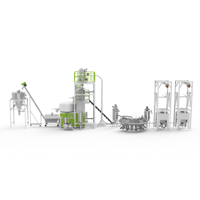
Industry-standard 304 stainless steel pipelines provide excellent durability for most plastic resins. The smooth internal finish minimizes friction, and the material resists corrosion from ambient plant conditions. However, processing highly abrasive materials like glass-filled nylon, ceramic powders, or metal-injected molding feedstocks requires specialized alloys or glass-lined pipes. These upgraded materials resist internal scouring and significantly extend the maintenance intervals of the pipeline network. Standard 304 stainless steel might wear through at a 90-degree elbow in a matter of months when conveying 30% glass-filled materials, whereas a specialized wear-resistant elbow can last years.
At the machine hopper level, rigid piping gives way to flexible connections. Strategic deployment of antistatic hoses prevents static discharge and allows for minor machine realignments. You must audit a supplier’s material certifications and wall-thickness specifications to ensure long-term durability across both rigid and flexible segments. A common mistake is using standard PVC flex hose, which quickly builds up a static charge, causing material to bridge and blocking the feed throat. True antistatic hoses feature an embedded copper wire that must be properly grounded to the machine frame.
Overhead structural engineering requires careful evaluation. Installing overhead stainless steel pipe networks demands precise weight load calculations. The support structures must include vibration dampening to protect the pipe joints from the constant pulsing of the vacuum pumps. Space-saving gantry supports keep the factory floor clear while providing secure routing for the delivery lines. When evaluating a supplier, ask to see their structural mounting plans. They should use heavy-duty strut channels and cushioned pipe clamps rather than cheap U-bolts that can crush the thin-walled stainless tubing.
Evaluating technical thresholds requires analyzing the chosen vacuum delivery method. Dilute phase conveying suspends the material in a high-velocity air stream, making it ideal for standard resins over short to medium distances. Dense phase conveying moves material in slower, heavier plugs, which protects fragile materials from impact degradation and reduces wear on the pipes. Dense phase systems require specialized pressure vessels and precise air injection controls, making them more complex but highly beneficial for specific applications.
You need a reliable framework for evaluating a supplier’s maximum horizontal distance claims. Validating 100-meter delivery claims requires reviewing their pump curves and pressure drop calculations. Never accept distance claims without reviewing the underlying engineering math based on your specific material bulk density. A side channel blower might easily convey virgin ABS pellets 50 meters, but fail completely when trying to pull heavy regrind over the same distance. The supplier must prove their pump selection matches your worst-case conveying scenario.
Furthermore, vertical lift heavily impacts the overall conveying capacity. Pushing material up two stories to a mezzanine-mounted dryer consumes significantly more vacuum power than moving it horizontally across the shop floor. The supplier's calculations must account for every vertical foot, every elbow, and every diverter valve in the system to guarantee the material will not stall in the lines.
Precise material routing depends entirely on the mechanical reliability of valves and diverters. Pneumatic diverter valves generally offer faster response times and tighter sealing integrity compared to motorized alternatives. They require less maintenance and handle high-cycle operations effectively. When a machine calls for material, the diverter must actuate instantly to open the correct path before the vacuum pump engages.
Material selectors frequently become failure points in poorly designed systems. Seal wear and mechanical jamming disrupt the entire production schedule. If a seal leaks, the vacuum drops, and the material stalls. Top-tier suppliers engineer around these risks by utilizing hardened seals, self-cleaning valve bodies, and accessible maintenance ports. They design manifolds that allow operators to quickly swap out a worn seal without dismantling the entire distribution hub.
Consider the design of a multi-station material distribution manifold. It acts as a switchboard, allowing any silo to feed any machine. The internal tolerances of this manifold must be exact. If pellets get trapped between the moving plate and the stationary ports, the manifold will jam. High-quality manifolds use inflatable seals or precision-machined shear plates to cut through trapped pellets without damaging the mechanism.
The central control console acts as the brain of the central feeding system. It must interact continuously with field sensors to manage vacuum levels dynamically. Closed-loop pneumatic controls maintain consistent material velocity regardless of the active delivery route. This dynamic adjustment prevents line plugging when routing distances change. For example, conveying material to Machine 1 (10 meters away) requires less vacuum than conveying to Machine 20 (80 meters away). The control system must adjust the pump speed via a variable frequency drive (VFD) or modulate a bypass valve to maintain the optimal air-to-material ratio for each specific route.
Modern control consoles utilize programmable logic controllers (PLCs) paired with intuitive human-machine interfaces (HMIs). The software must be robust enough to handle simultaneous demand signals from multiple machines. If five injection molding machines call for material at the exact same time, the PLC must queue the requests based on priority, hopper levels, and available vacuum pumps. It must execute these transfers sequentially without starving any machine of resin.
Pipeline control must integrate seamlessly with upstream conditioning equipment. The system must sequence delivery to ensure dried and dehumidified materials do not re-absorb moisture during transit. The control logic should clear the lines completely after each transfer cycle. Leaving dried polycarbonate sitting in an ambient pipe for twenty minutes will ruin its moisture profile, leading to defective parts. The purge cycle is a non-negotiable feature for any system handling hygroscopic resins.
Maintenance automation reduces operator burden and improves reliability. The control system should manage automated filter cleaning, safety blowback sequences, and routine dust collection dumps. When evaluating a supplier, assess the software architecture of their central console. Look for open communication protocols, real-time diagnostic dashboards, and automated fault isolation capabilities.
A well-programmed central console will execute the following automated sequences without human intervention:
Standardized, modular pipe runs offer a lower upfront barrier to entry. However, they rarely match the operational efficiency of a custom-engineered holistic solution. Rigid modular kits force unnatural routing paths, increasing the number of elbows and elevating the risk of pressure drops. Every 90-degree elbow adds the equivalent of roughly 20 feet of straight pipe resistance to the system. Forcing a layout to fit pre-cut pipe lengths often results in a convoluted network that strains the vacuum pumps and degrades the material.
A reliable central feeding system manufacturer conducts a rigorous site audit phase. This process should include 3D scanning and interference mapping to avoid existing HVAC, electrical, and structural elements. Spatial optimization through custom overhead pipeline routing maximizes usable floor space and significantly improves safety on the manufacturing floor. By mapping the facility in 3D, the engineers can design sweeping, long-radius bends that gently guide the material around obstacles, rather than relying on sharp, standard-issue elbows.
The site audit must also account for the specific raw material conditions. Are you bringing in material via 25kg bags, gaylords, or bulk trucks? The intake points must be ergonomically designed and integrated into the central pipeline network. Bag dump stations require integrated dust collection to protect operators, while bulk truck unloading requires massive, high-capacity lines that can handle thousands of pounds per hour without overwhelming the central filters.
Facilities grow, and the pipeline network must accommodate future machine additions. Suppliers should design pipeline manifolds and install blind-flanged tees during the initial build. This foresight allows you to connect new processing lines later without requiring total system shutdowns. Cutting into an active stainless steel pipeline to add a branch is messy, time-consuming, and introduces metal shavings into the material flow. Pre-planning connection points eliminates this risk.
Scaling the pipeline network eventually tests the limits of the central vacuum pumps. You must plan for modular pump upgrades from day one. Discuss the maximum volumetric capacity of the initial pump skid and map out the exact upgrade path required when you add future processing machines. A well-designed system will allow you to simply drop in an additional vacuum pump and tie it into the existing manifold, rather than ripping out and replacing the original equipment.
| Feature | Custom-Engineered Layout | Standard Modular Kit |
|---|---|---|
| Routing Efficiency | Optimized for minimal elbows and shortest paths | Constrained by pre-cut lengths, often requires extra bends |
| Pressure Drop | Calculated and minimized for specific facility | Higher due to non-optimized routing |
| Installation Time | Longer engineering phase, faster physical install | Quick to ship, often requires field modifications |
| Scalability | Pre-planned expansion nodes included | Often requires cutting and retrofitting existing lines |
Implementation risks threaten production timelines and output quality. Pipeline clogging at elbows, abrasive wear-through, and vacuum leaks at coupling joints represent the most common failures. Material bridging in the hoppers also disrupts the automated flow. A vacuum leak at a single poorly installed pipe clamp can degrade the suction power across the entire network, causing intermittent stalling that is incredibly difficult to troubleshoot.
Mitigation requires specific engineering choices during the design phase. You must specify long-radius elbows to reduce impact friction. Reinforced impact zones protect high-wear areas, while heavy-duty clamp connections eliminate vacuum leaks at the pipe joints. For highly abrasive materials, consider specifying elbows with a specialized wear-back design, where a small pocket of material is allowed to accumulate, meaning the incoming pellets impact other pellets rather than the steel pipe wall.
Another major risk is filter blinding. If the central dust collector is undersized or the automated cleaning pulses are ineffective, the filter media will clog with fines. This chokes the airflow, reducing conveying capacity and eventually stalling the system. Ensure the supplier sizes the filtration unit based on the dustiest material you plan to run, not just the average clean pellet.
Pipeline control and site delivery represent the most critical, yet frequently under-evaluated, components of bulk material handling. Prioritize engineering rigor over component-level savings to ensure long-term operational stability. A poorly routed pipe network will bottleneck even the most advanced processing machinery, leading to endless maintenance headaches and degraded product quality.
Filter your potential suppliers based on their ability to provide custom layout engineering. Demand transparent pneumatic control logic and verifiable distance and throughput capabilities. A true manufacturing partner will prove their claims with hard engineering data, not just sales brochures.
Take these actionable next steps to secure the right system:
A: Maximum distance depends heavily on pump size, pipe diameter, and material bulk density. For typical 304 stainless steel setups conveying standard plastic pellets, 100 meters horizontally is a standard benchmark. Pushing beyond this requires specialized dense-phase conveying or booster pumps to maintain adequate pressure.
A: Preventing clogs requires maintaining an optimal air-to-material ratio. You must use correct pipe sizing and specify long-radius elbows to reduce friction. Furthermore, the central console must execute automated purge cycles to clear the lines completely after every transfer sequence.
A: Manufacturers design, engineer, and build the proprietary hardware and control consoles in-house. They own the core technology. Integrators purchase third-party components from various brands and assemble them. Manufacturers typically offer better software integration and direct technical support.
A: Friction between plastic pellets and pipe walls generates significant static electricity. Without antistatic hoses, this buildup causes material bridging, where pellets stick together and block flow. It also risks dust explosions and can severely disrupt the electronic sensors monitoring the hopper levels.
A: The console receives low-level signals from machine hoppers. It then opens specific cut-off valves and diverters to create a routing path. Next, it activates the vacuum pump to pull material. Finally, it triggers dust removal and dehumidification protocols before purging the line clean.


