
- All
- Product Name
- Product Keyword
- Product Model
- Product Summary
- Product Description
- Multi Field Search
 English

Views: 0 Author: Site Editor Publish Time: 2026-07-26 Origin: Site


Transitioning from decentralized, machine-side material loading to a fully automated facility involves significant operational disruption if not managed correctly. Plant managers face a critical dilemma: the urgent need to reduce material waste, labor costs, and floor congestion versus the unacceptable risk of halting production for a massive facility-wide installation. Ripping out existing infrastructure all at once often leads to missed production quotas and unacceptable downtime.
A phased implementation strategy allows facilities to upgrade their material handling infrastructure incrementally. This approach validates return on investment early, minimizes downtime, and ensures seamless integration of a whole plant central feeding system without compromising current production quotas. By breaking the project into manageable stages, engineering teams can systematically replace manual loading processes while keeping core manufacturing lines running smoothly.
Upgrading material handling infrastructure requires clear baseline metrics to measure success. Facility managers must define exact performance indicators before installing a centralized feeding system. Establishing these baselines allows plant operators to objectively evaluate the performance of automated conveying against legacy manual loading methods. You need hard data to justify the expansion phases.
Executing a rip-and-replace strategy is logistically impossible in a 24/7 manufacturing environment. Shutting down an entire injection molding or extrusion floor to install overhead piping and central vacuum units halts revenue generation. Phased rollouts solve this by keeping the majority of machines running. Installation crews can route main vacuum headers and install silos without interfering with active production lines. Final machine connections are then scheduled during routine maintenance windows or weekend shifts, ensuring continuous output.
| Implementation Strategy | Downtime Impact | Risk Level | Resource Allocation |
|---|---|---|---|
| All-at-Once (Rip & Replace) | High (Days to Weeks) | Severe | Requires massive external contractor presence |
| Phased Rollout | Low (Hours per machine) | Minimal | Manageable with internal maintenance teams |
Automated material handling introduces new technology to the production floor. Phased rollouts allow machine operators and maintenance teams to adapt to new automated controls and manifold stations gradually. Instead of overwhelming the staff with a facility-wide system change, a step-by-step approach facilitates hands-on learning. Operators master receiver calibration, filter maintenance, and HMI navigation during minor line conversions. This hands-on exposure significantly reduces user error when the full system comes online.
The foundation of a reliable conveying network begins with auditing current and projected material usage. Engineering teams must document bulk densities, flow characteristics, and the abrasiveness of all processed resins. Required conveying distances and vertical lifts dictate pipe sizing and pump capacities. Failing to account for high-bulk-density materials or long horizontal runs results in frequent line blockages and inadequate material flow to the hoppers.
| Material Type | Typical Bulk Density (lb/ft³) | Conveying Challenge | Recommended Pipe Material |
|---|---|---|---|
| Virgin PET Pellets | 45 - 50 | Dust generation at high speeds | Standard Stainless Steel |
| Glass-Filled Nylon | 35 - 45 | Highly abrasive, wears out elbows | Hardened Steel / Ceramic Lined |
| Regrind Flake | 20 - 30 | Prone to bridging and interlocking | Oversized Stainless Steel |
Proper layout planning requires mapping the facility's physical footprint into logical zones. This process is similar to row mapping in large-scale agriculture, plotting optimal vacuum line pathways and future drop points. Effective zoning minimizes pressure drops and prevents line routing interference with overhead cranes or existing HVAC infrastructure. Planners must design the pipe network to accommodate current machine placements while leaving accessible connection points for future expansion. Avoid short-radius 90-degree elbows at all costs; they kill vacuum pressure and destroy pellets.
Selecting the right equipment partner dictates the long-term viability of the project. Assess vendors based on their ability to provide modular systems, open-architecture PLC controls, and local integration support. Avoid manufacturers that lock facilities into proprietary, non-expandable hardware. A qualified central feeding system manufacturer will offer transparent engineering data and support a phased integration strategy rather than pushing for an all-at-once installation. Look for partners who understand the realities of factory floor integration.
Initial installations must include oversized core components to prevent future bottlenecks. Specifying larger central vacuum pumps, blower units, and dust collection systems during Phase 1 supports the final facility-wide rollout without requiring costly future tear-outs. Installing a pump sized only for the pilot line guarantees that the equipment will need to be replaced or duplicated when connecting additional machines. Oversizing the main vacuum header pipe by one or two inches during Phase 1 saves immense labor later.
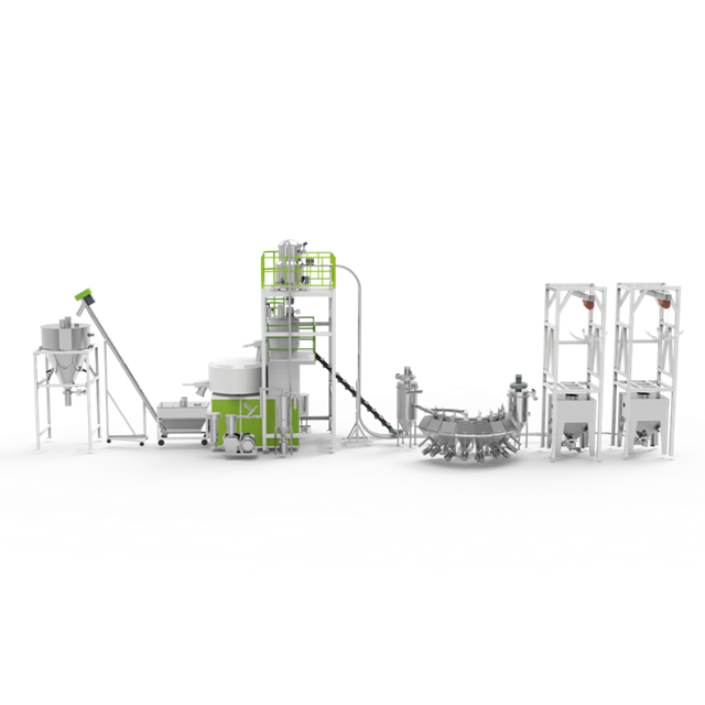
The pilot installation serves as the proving ground for the new infrastructure. Select an initial machine cluster that offers high-volume, single-material processing. These lines provide the fastest measurable return on investment with the lowest cross-contamination risk. By isolating the pilot to a specific, high-throughput zone, engineers can easily track labor reduction and material savings against the previously established baselines. Do not choose your most complex, multi-color line for the pilot.
Phase 2 focuses on routing the primary material lines and setting up the central material room. This includes erecting outdoor silos, installing indoor day bins, and configuring central drying hoppers. The initial vacuum network is established, connecting the central pump station to the pilot machine cluster. This backbone must be installed with future branch connections in mind.
System parameters require careful adjustment to handle the initial stage of the project. Focus on conveying raw base materials before introducing complex, multi-component recipes. Technicians must set the appropriate vacuum pressure, conveying times, and line-clearing intervals. Establishing stable conveying for virgin resins provides a reliable baseline before attempting to convey challenging regrind or highly abrasive glass-filled polymers. Proper line clearing prevents plugs during shutdown.
Monitor conveying speeds closely to ensure material is not degrading or creating excessive dust, commonly known as angel hair in plastics processing. High-velocity conveying causes friction, which melts the outer layer of the plastic pellets. Validate that the pilot line achieves the projected reduction in manual loading labor and material waste. If the pilot line fails to meet the success metrics, parameters must be adjusted before scaling the system further. Check the central filter daily during this phase to gauge dust generation.
The pilot line functions as a low-risk environment for maintenance staff. Operators learn the calibration of receivers, central filters, and HMI control screens without the pressure of managing the entire plant's material flow. This hands-on experience builds confidence and ensures that the maintenance team can troubleshoot common issues independently. They learn how to clear a plugged line, clean a receiver screen, and reset a vacuum fault.
Once the pilot line proves successful, the facility can begin branching off the main vacuum line to secondary and tertiary machine clusters. This expansion requires careful balancing of the vacuum network to ensure adequate suction reaches the furthest machines. Installers must maintain proper pipe gradients and utilize long-radius bends to minimize material degradation as the conveying distances increase. Hangers and supports must be reinforced to handle the dynamic load of material surging through the pipes.
Scaling introduces the risk of cross-contamination during material changeovers. Facilities must implement automated material selection stations, RFID-coded manifold connections, and line-clearing purge valves to ensure material purity. Adapting conveying parameters becomes necessary to handle variations in bulk densities as lines transition between virgin material, regrind, color concentrates, and specific performance additives. Dedicated lines for highly sensitive or incompatible materials may be required.
| Manifold Type | Contamination Risk | Changeover Speed | Best Application |
|---|---|---|---|
| Manual Cam-Lock | Moderate (Human Error) | Slow | Low-frequency material changes |
| RFID-Verified Manual | Low | Medium | Standard multi-material plants |
| Fully Automated Valve Matrix | Zero | Instant | High-frequency, complex recipe plants |
A fully scaled system must communicate with the broader facility infrastructure. Connecting the central feeding system PLC with the facility's ERP or MES enables real-time inventory tracking. This integration allows for automated silo reordering based on actual consumption rates, eliminating manual inventory counts and preventing unexpected material shortages. The PLC can also track pump run hours and trigger maintenance work orders automatically.
Continuous operation requires adjusting air-to-material ratios across different distances and vertical lifts. Fine-tuning these parameters optimizes energy usage and minimizes pipe wear. Variable frequency drives (VFDs) on the vacuum pumps allow the system to ramp up suction for long-distance conveying and reduce power for machines located closer to the material room, maximizing energy efficiency. Dialing in the VFDs prevents pellet shattering caused by excessive terminal velocity.
Reliable operation depends on balancing continuous production with necessary downtime for preventive maintenance. Maintenance teams must establish strict schedules for filter cleaning, vacuum pump lubrication, and pipe inspection. Neglecting central dust filters leads to reduced suction power, increased conveying times, and eventual pump failure. Implementing differential pressure sensors across filters can trigger automated maintenance alerts before performance degrades.
Measure the operational savings against the initial baseline established in Phase 1. Factor in reduced scrap rates, lower energy bills, and reallocated labor. Tracking these metrics validates the success of the phased implementation and provides concrete data to justify further automation investments. Consistent monitoring ensures the system continues to operate at peak efficiency years after the final installation phase. Documenting these wins helps secure capital for future plant upgrades.
A: A phased implementation typically spans 6 to 12 months. The initial auditing and facility mapping take 3 to 4 weeks. Installing the core infrastructure and pilot line usually requires 4 to 8 weeks. Scaling to the rest of the facility is done in stages over the remaining months, scheduled during routine maintenance windows to avoid disrupting production.
A: Yes. Systems handle various materials by using proportioning valves at the machine throat or central blenders in the material room. Dedicated conveying lines are often used for dusty regrind to prevent cross-contamination, and parameters are adjusted to accommodate different bulk densities and prevent bridging in the hoppers.
A: Most facilities see a return on investment within 12 to 24 months. This rapid payback is driven by a significant reduction in manual labor, lower energy consumption compared to individual machine-side loaders, and a drastic decrease in material waste and floor sweepings.
A: Material degradation is prevented by controlling conveying velocity. Utilizing variable frequency drives (VFDs) on vacuum pumps ensures the air-to-material ratio is optimized. Additionally, using long-radius elbows in the piping network reduces friction and prevents the formation of angel hair and dust.
A: No. A phased approach is specifically designed to prevent facility-wide shutdowns. Main vacuum lines and silos are installed while machines run. Final connections to individual machines are scheduled during planned downtime, weekend shifts, or routine mold changes.
A: Prioritize manufacturers with extensive industry experience and custom engineering capabilities. Look for vendors that provide open-architecture PLC controls, modular equipment that allows for easy expansion, and robust post-installation support to assist with system calibration and operator training.


