
- All
- Product Name
- Product Keyword
- Product Model
- Product Summary
- Product Description
- Multi Field Search
 English

Views: 0 Author: Site Editor Publish Time: 2026-08-14 Origin: Site


High-end recycling machinery cannot compensate for poorly planned facility logistics. You can invest in the most advanced shredders and extruders on the market, but inefficient material flow will still lead to bottlenecks, cross-contamination, and degraded profit margins. When raw bales, wet flakes, and finished pellets cross paths improperly, the entire operation suffers from unnecessary downtime and safety hazards.
Facility managers face the complex challenge of balancing high-volume throughput with strict space constraints. You must account for varying feedstock quality while maintaining a strict separation between wet processing and dry extrusion zones. Without a logical spatial arrangement, material handling becomes chaotic, requiring excessive forklift movement and manual intervention that eats into operational efficiency.
Designing a logical facility layout optimizes the journey from raw bale intake to the final extruded product. A systematic approach to material flow ensures continuous operation, maximizes yield, and protects your equipment investments. By mapping every stage of the process, you build a foundation for a highly efficient, scalable, and safe recycling environment.
Evaluating flow efficiency requires tracking specific operational metrics on the plant floor. You should measure the total material travel distance from the intake dock to the shipping bay. Shorter distances reduce energy consumption, limit forklift wear, and decrease the probability of material spills during transit. Count the number of manual touchpoints required during processing. Fewer touchpoints indicate better automation, lower labor overhead, and reduced risk of human error in sorting or feeding stages. Overall equipment effectiveness (OEE) serves as the ultimate metric, reflecting how well your layout supports continuous machine uptime by minimizing starvation or overfeeding at individual machine centers.
Commercial-scale operations must prioritize continuous flow over batch processing. Batch processing creates start-and-stop cycles that strain motors, cause thermal inconsistencies in extrusion, and lead to uneven wear on granulator blades. Continuous flow keeps material moving steadily through the complete plastic recycling plant. This steady state maximizes throughput, ensures uniform product quality, and stabilizes the electrical load on your facility's main breakers.
Value chain mapping helps visualize this continuous movement. Trace the material journey starting from raw intake. Follow it through the progressive stages of shredding, friction washing, and thermal drying. Finally, map the path to the final pellet output. This visual exercise quickly highlights redundant movements, areas where material accumulates unnecessarily, and pinch points where a single conveyor failure could halt the entire operation.
Unidirectional material movement is non-negotiable in high-grade recycling. Processed flakes or finished pellets must never cross paths with raw, contaminated bales. If a forklift drives through a dirty intake zone and then enters the clean packaging area, it tracks dirt, oil, and debris that can ruin an entire batch of premium pellets. The flow must move forward in one continuous direction, physically separating the "dirty" front end from the "clean" back end.
Implementing physical barriers enforces this unidirectional flow. Use distinct HVAC zones to prevent airborne dust, paper labels, and fine dirt from the shredding area from settling on clean flakes in the drying zone. Designate dedicated forklift routes. One fleet handles inbound dirty bales, while a separate fleet manages clean finished goods. Paint clear traffic lanes on the floor, install physical guardrails to prevent route deviations, and use rapid-roll doors between zones to maintain air pressure differentials.
Point-of-generation segregation stops contamination before it spreads across the plant floor. Establish strict protocols for capturing internal waste streams immediately. When fines, off-spec material, wash-water sludge, or extrusion purge generate, isolate them at the source. Use dedicated collection bins, localized vacuum systems, and under-belt catch pans. This prevents secondary waste from re-entering and contaminating the primary production line, saving hours of cleanup and preventing equipment damage.
Sizing the intake yard requires analyzing daily throughput requirements and delivery schedules. A facility processing 20 tons per day needs enough floor space to stage at least two days of buffer stock. This prevents production halts if inbound deliveries face weather or transit delays. Calculate the footprint of standard bales and allocate space accordingly, leaving ample room for safe stacking, retrieval, and wire-cutting stations. Ensure the concrete slab in this area is rated for heavy, repetitive forklift loads.
Forklift traffic flow demands careful logistical planning. Separate inbound delivery routes from internal material feeding routes. When delivery trucks unload, they should not block the forklifts actively feeding the primary shredder. Congestion in the intake yard causes immediate delays down the line. Implement a one-way traffic system for all mobile equipment in the storage yard, utilizing wide turning radii to accommodate long trailers and heavy-duty loaders.
Designate specialized drop-off and storage zones based on feedstock types. Segregate post-industrial scrap from highly contaminated post-consumer bales. Post-industrial scrap often requires less aggressive pre-washing and sorting. By keeping these streams separate, operators can streamline early sorting, adjust line parameters quickly based on the specific material batch being processed, and avoid cross-contaminating clean industrial scrap with municipal waste.
Selecting the right conveyor type depends entirely on the material state and the physical layout of the building. Belt conveyors work best for moving heavy, bulky bales and loose plastic bottles up to the initial shredder. Screw conveyors excel at transporting wet, shredded flake vertically or at steep angles out of wash tanks. Pneumatic conveying systems are ideal for moving dry, lightweight flakes over long distances across the facility roofline, freeing up valuable floor space for maintenance access.
Integrating in-line pre-treatment protects downstream machinery and improves overall yield. Install trommels to remove loose dirt, glass, and rocks before shredding. Place heavy-duty magnetic separators over conveyor belts to catch rogue ferrous metals that could shatter granulator blades or damage extruder screws. Optical sorters help separate non-target plastics early in the process, reducing the load on the downstream wash line.
Design bypass chutes for these pre-treatment stations. If a magnetic separator requires maintenance or an optical sorter needs recalibration, a bypass chute allows the primary feed to continue running temporarily. This redundancy prevents a minor sensor cleaning from halting the entire facility, maintaining the continuous flow required for profitable operation.
| Conveyor Type | Optimal Material State | Primary Plant Location | Maintenance Considerations |
|---|---|---|---|
| Slider Bed Belt | Whole bales, loose bottles | Intake, manual sorting lines | Requires regular tracking adjustments and belt tensioning. |
| Shafted Screw Auger | Wet, heavy friction-washed flake | Between sink-float tanks and dryers | Prone to wrapping with long films; requires accessible clean-out ports. |
| Pneumatic Blower | Dry, lightweight flake or pellets | Post-dryer to extrusion, packaging | Filters need frequent cleaning; elbows wear out from abrasion. |
| Vibratory Feeder | Granulated flake, fines | Feeding optical sorters or extruders | Springs and isolation mounts require periodic inspection. |
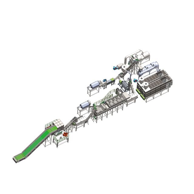
A commercial plastic washing line demands specific, heavy-duty infrastructure. You must incorporate deep, sloped trench drains directly into the concrete foundation before equipment installation. Water filtration loops, including rotary screens and dissolved air flotation (DAF) units, require dedicated square footage adjacent to the main line. Clean-in-place (CIP) water systems need accessible plumbing headers and high-pressure hookups. Failing to plan for these utilities results in expensive retrofitting costs, exposed piping, and compromised equipment placement.
Moving wet, heavy friction-washed flake through sink-float tanks presents logistical challenges. The material holds significant water weight, changing its flow characteristics. Use robust dewatering augers to lift the material out of the tanks. Ensure these augers feature proper drip pans and return channels. Water dripping onto the floor creates severe slip hazards, fosters bacterial growth, and degrades the concrete slab over time.
Implement a comprehensive spill control and containment plan. Process water, caustic cleaning agents, and micro-debris will inevitably escape during routine maintenance and screen changes. Install secondary containment berms around chemical dosing stations and hot wash tanks. Use sloped floors directing runoff into designated catch basins equipped with fine mesh screens. Maintaining a dry floor environment ensures local environmental compliance and protects worker safety.
Assess vendors based on their ability to customize equipment footprints to your specific building. Building constraints, such as load-bearing columns and low roof trusses, often dictate the layout. A reliable plastic washing line manufacturer will offer L-shaped, U-shaped, or Z-shaped configurations to fit around existing structural elements. Avoid vendors who only offer rigid, straight-line setups that force you to undergo expensive building modifications or compromise on maintenance clearances.
Centralized control panels and modular equipment designs are critical for long-term plant viability. Modular designs allow you to add an extra friction washer, a secondary sink-float tank, or a thermal dryer later without a complete facility redesign. Centralized control panels reduce the walking distance for operators, allowing one person to monitor water temperatures, motor loads, and throughput from a single vantage point, rather than running between isolated machine stations.
The chosen manufacturer must provide detailed utility schematic overlays during the early spatial layout phase. You need exact connection points for water inlet, wastewater discharge, high-voltage electricity, and compressed air before pouring concrete. Guessing these locations leads to exposed pipes, tripping hazards across the production floor, and inefficient utility routing that increases installation costs.
Buffer silos play a critical role between the thermal drying stage and the extrusion stage. Washing lines and extruders rarely operate at the exact same speed or experience downtime simultaneously. If the wash line produces 1,200 kg/hr but the extruder only handles 1,000 kg/hr, the excess material needs a place to go. Without a buffer, the washing line must shut down, wasting energy, disrupting the thermal equilibrium of the hot wash, and causing material to settle in the pipes.
Calculate buffer capacity based on this throughput mismatch and anticipated maintenance intervals. A standard rule is to install enough surge hopper capacity to hold at least two to four hours of production. This allows the washing line to run continuously even if the extruder stops for a screen change, die face cleaning, or minor maintenance. Properly sized buffers smooth out production spikes, blend different batches for consistent bulk density, and keep the entire line balanced.
The spatial requirements for a plastic pelletizing system depend heavily on the chosen cooling method. Water ring and underwater pelletizers require a compact footprint but need vertical clearance for centrifugal dryers and vibrating classifiers. Strand cooling processes demand significant linear length for the water bath and air knives. Map this footprint carefully to ensure operators have room to string the melt strands safely and clear blockages without risking burns.
Map the flow of finished pellets into bagging stations, octabins, or storage silos. Proximity to outbound loading docks is essential. The shorter the distance between the bagging station and the shipping truck, the lower the risk of forklift accidents and damaged packaging. Use pneumatic blowers to move pellets to silos located directly above the loading bays, allowing for gravity-fed truck loading.
Integrate physical containment layouts to prevent pellet loss. Operation Clean Sweep protocols require specific infrastructure at packaging zones.
Logistical planning must include airflow and HVAC integration. The extrusion zone generates significant heat from barrel heaters and mechanical friction. Without proper ventilation, ambient temperatures rise rapidly, causing electrical cabinets to overheat and creating an unsafe working environment. Plan the layout to position high-heat equipment near exterior walls where heavy-duty exhaust fans and makeup air units can operate efficiently.
Local exhaust ventilation (LEV) is required to capture volatile organic compounds (VOCs) and melt-odors. High-temperature processing releases fumes that must be extracted directly at the extruder die head, vacuum degassing ports, and screen changers. Route ductwork carefully to avoid interfering with overhead bridge cranes, pneumatic conveying lines, or lighting fixtures.
Establish strict separation boundaries between high-heat extrusion zones and climate-controlled storage areas. Finished pellets must cool completely before packaging. If stored too close to the extruders, ambient heat can cause the pellets to re-soften, clump together in the bags, and absorb ambient odors, ruining the final product quality and leading to customer rejections.
Compact equipment layouts save floor space but often sacrifice critical maintenance access. You must leave adequate clearance around all machinery. Technicians need physical room to pull heavy extruder screws, replace granulator blades using lifting hoists, and service wash line screens. If a machine is pushed too close to a wall or structural column, a standard two-hour maintenance task turns into a full-day teardown, destroying your OEE metrics.
Design adjustable operator platforms for elevated equipment like sink-float tanks and large surge hoppers. Localized task lighting ensures operators can inspect material quality safely and identify blockages. Designate clear pedestrian walkways using physical bollards and high-visibility epoxy paint. These walkways must remain physically isolated from heavy machinery zones and forklift paths to prevent workplace accidents and ensure safe evacuation routes.
Successful material flow planning requires treating the facility as a single, interconnected organism rather than a collection of isolated machines. Every conveyor, buffer silo, and forklift route impacts the overall efficiency of the operation. By mapping the flow meticulously, you eliminate bottlenecks, protect product purity, and maximize your return on equipment investment.
A: The U-shaped layout is generally best for facilities with shared shipping and receiving docks, optimizing forklift travel. Linear layouts work best for strict contamination control in long buildings, keeping dirty intake far from clean output. L-shaped layouts adapt well to awkward footprints but require careful corner management for conveyors.
A: A standard 1,000 kg/hr capacity line typically requires between 1,500 and 3,000 square meters. This baseline factors in raw material storage, processing equipment, water treatment systems, buffer zones, maintenance clearances, and finished goods warehousing.
A: Install adequately sized buffer silos and surge hoppers between the stages. These buffers hold excess flake, allowing the washing line to continue running temporarily if the extruder requires a screen change or minor maintenance, preventing full-plant shutdowns.
A: Moisture re-entering dried flakes before extrusion leads to poor pellet quality, gas inclusion, and polymer degradation. Additionally, water tracking into electrical panels or dry-handling areas creates severe safety hazards and degrades the concrete floor.
A: Look for modular design capabilities, custom conveyor engineering, and the provision of detailed utility consumption and footprint schematics during the proposal phase. They must adapt their machinery to your building constraints, not force expensive facility modifications.
A: Minimizing physical travel distances reduces forklift fuel usage. Utilizing gravity feeds where possible and optimizing pneumatic conveying routes directly reduce the power consumption and mechanical strain on auxiliary motors and blowers.


