
- All
- Product Name
- Product Keyword
- Product Model
- Product Summary
- Product Description
- Multi Field Search
 English

Views: 0 Author: Site Editor Publish Time: 2026-07-25 Origin: Site


Scaling plastics manufacturing or extrusion operations introduces exponential complexity in material handling. Manual or decentralized feeding quickly becomes a primary bottleneck for throughput and product quality. Managing multiple raw materials across dozens of injection molding machines leads to high labor costs, increased risk of cross-contamination, material spillage, and inconsistent drying times. These variables directly impact part quality, leading to higher scrap rates and unpredictable production cycles.
Transitioning to a whole plant central feeding system consolidates material storage, drying, and distribution into a single automated network. This infrastructure upgrade removes the physical chaos from the production floor, replacing individual hopper loaders and standalone dryers with a streamlined, centralized approach. This guide breaks down the architectural requirements, evaluation criteria, and implementation risks of deploying a centralized system for multi-line facilities.
Facility managers must understand how a single system can physically and logically route distinct polymers, regrinds, and additives to specific machines without bottlenecks. The architecture dictates the flow, ensuring the right material reaches the right machine at the exact moment it is needed. When dealing with high-volume production, relying on manual material handlers moving gaylords across the floor is a recipe for disaster. A centralized network eliminates this variable entirely.
Maintaining material purity requires dedicated stainless steel pipelines. The "one machine, one pipe" design philosophy ensures each injection molding or extrusion line has a direct, uncontaminated route from the material source. This prevents residual pellets from mixing with virgin resins during changeovers. Stainless steel offers the durability needed to withstand the abrasive nature of glass-filled polymers while providing a smooth internal surface to reduce friction. Using 304 or 316-grade stainless steel prevents the degradation of the pipe walls, which otherwise leads to contamination.
Sealed circuits are equally critical for preventing moisture re-absorption and dust accumulation during transit. Once hygroscopic materials exit the central dryer, they must remain in a controlled environment. A closed-loop conveying system utilizes dry air to transport the resin, ensuring the dew point remains stable from the drying hopper to the machine throat. This eliminates the risk of splay or structural weakness in the final molded part. If ambient plant air is used for conveying, the material will immediately pull moisture from the environment, negating the entire drying process.
Modern production facilities rarely run a single resin. Automated manifold stations and material distribution stations act as the physical switchboards of the plant. Operators can physically or electronically connect specific material silos to designated machine lines. This modularity allows a single plant to run ABS, polycarbonate, PET, and various regrinds simultaneously across different zones. The manifold must be designed with quick-disconnect fittings and clear labeling to prevent operator error during material changeovers.
Conveying dynamics differ vastly between plastic granules and fine powders. Granules flow relatively easily under standard vacuum pressure. Powders, such as PVC compounds, require specialized powder vacuum receivers, anti-blocking measures, and advanced dust collection systems. Powders tend to bridge or pack tightly, necessitating fluidization pads or mechanical agitation at the source to maintain a steady flow rate. If you try to convey powder through a system designed for pellets, the filters will blind immediately, and the vacuum pumps will stall.
Integrating proportional valves allows for precise mixing of virgin materials, masterbatch, and regrind directly at the machine throat. These valves alternate between two material sources based on a programmed ratio, ensuring a homogenous blend enters the feed screw without requiring a separate offline blending step. This inline mixing reduces material handling steps and ensures consistent color and physical properties in the finished product.
Large facilities often separate production into distinct rooms, chambers, or physical plant zones based on cleanroom requirements or product lines. Central feeding systems cross-communicate and transport raw materials across these boundaries. The central control unit monitors demand across all zones, sequencing the vacuum pumps to serve machines based on priority and distance. This requires a robust industrial network, typically utilizing Ethernet/IP or Profinet, to ensure signal integrity across long distances.
Routing pipelines through structural firewalls and across isolated production bays introduces challenges in maintaining pressure and feed consistency. Engineers must calculate the total equivalent pipe length, accounting for vertical lifts and horizontal runs. Long distances require strategically placed booster stations or larger vacuum pumps to ensure the material maintains sufficient velocity without degrading or creating excessive dust. Every 90-degree elbow adds significant equivalent length to the run, so routing must be as direct as possible.
Central vacuum pumps generate the negative pressure required to convey plastic granules and powders through the pipeline network. Instead of pushing the material, the system pulls it, which minimizes the risk of material leaks into the ambient plant environment. Heavy-duty positive displacement blowers or side channel blowers provide the necessary airflow and vacuum depth. Roots-style blowers are typically preferred for long distances and heavy materials due to their ability to generate deep vacuum levels consistently.
The system prioritizes feeding schedules based on real-time hopper level sensors across 36+ injection molding machines. When a sensor detects a low material level, it sends a signal to the central PLC. The automated distribution logic queues the request, opens the appropriate material valve, activates the vacuum pump, and fills the receiver. This continuous monitoring prevents machine starvation and ensures uninterrupted production cycles. The logic must account for purge times and filter cleaning cycles to maintain overall system efficiency.
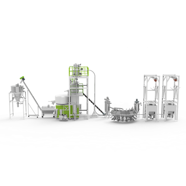
Defining the performance metrics that dictate whether a centralized feeding system will meet current and future production targets requires looking beyond basic specifications. Plant engineers must evaluate throughput, contamination control, and energy consumption. A poorly designed system will choke under peak load, causing widespread machine downtime.
The relationship between vacuum motor sizing, pipe diameter, and maximum conveying distance determines the system's physical limits. Undersized pipes create bottlenecks, while oversized pipes reduce air velocity, causing material to drop out of the airstream and plug the line. Engineers must calculate the required air volume and pressure drop for the longest and most demanding run in the facility. A common mistake is sizing the system for average throughput rather than peak demand.
Establishing baselines for calculating required kg/hr throughput per line prevents machine starvation. You must evaluate the maximum shot size and cycle time of each injection molding machine. The conveying system must deliver material faster than the machine consumes it, factoring in the time required for line clearing and filter cleaning cycles. If a machine requires 500 kg/hr, the conveying line serving it should ideally be rated for at least 650 kg/hr to provide a safety margin.
Automated line-clearing, or purge functions, are mandatory after each conveying cycle. Once the vacuum receiver is full, a purge valve opens at the material source, allowing clean air to sweep the remaining pellets out of the pipeline and into the receiver. This ensures the pipe is completely empty before the next material type is conveyed through a shared manifold segment. Without this feature, residual pellets will mix with the next batch, causing immediate quality failures.
Centralized dust collection and filtration units maintain material integrity and protect the vacuum pumps. As pellets collide with pipe walls, they generate dust and "angel hair" (long strands of melted plastic). Central filters capture these particulates before they reach the blower. Regular automatic blowback cycles clean the filter cartridges, maintaining optimal airflow and preventing cross-contamination of dust between different resin batches. High-efficiency cyclone separators are often installed ahead of the main filters to drop out heavy dust loads.
Comparing the energy footprint of decentralized individual loaders versus a centralized variable frequency drive (VFD) vacuum system reveals significant savings. Individual loaders run constantly, drawing peak amperage during every startup. A centralized system utilizes VFDs to adjust the motor speed based on real-time demand. If only three machines require material, the pump ramps down, consuming a fraction of the power. This dynamic scaling is where the true operational savings are realized.
Centralized systems also reduce ambient heat and noise on the production floor. Moving the vacuum blowers and desiccant dryers to a dedicated utility room lowers the cooling load on the plant's HVAC system. This improves operator comfort and creates a safer, quieter working environment. Blowers generate significant heat and noise; isolating them behind acoustic enclosures or in separate rooms is standard practice in modern facility design.
| Operational Metric | Decentralized Individual Loaders | Centralized Feeding System |
|---|---|---|
| Energy Consumption | High (Multiple small motors running constantly) | Low (VFD-controlled central pumps optimize power) |
| Floor Space Utilization | Cluttered (Material bags and dryers at every machine) | Optimized (Storage and drying moved to utility room) |
| Maintenance Burden | Labor-intensive (Servicing dozens of individual filters) | Streamlined (Centralized filter banks and pumps) |
| Ambient Noise Levels | High ambient noise on the production floor | Quiet production floor (Pumps isolated in utility rooms) |
| Material Spillage Risk | High (Manual loading at each machine) | Virtually Zero (Sealed vacuum conveying) |
Breaking down the specific technological components differentiates entry-level setups from enterprise-grade systems. The control architecture and safety mechanisms dictate the reliability of the entire plant. You cannot afford a control system that crashes or fails to report sensor errors accurately.
Centralized touch-screen interfaces (HMI) provide real-time diagnostics and fault alarms. Operators can view the status of every machine, vacuum pump, and material silo from a single location. Visual flow diagrams highlight active conveying routes, making it easy to identify blockages or sensor failures immediately. The HMI should offer multi-level password protection to prevent unauthorized personnel from altering conveying parameters or purge times.
Integration capabilities with existing ERP or MES software allow for accurate material consumption tracking. The central feeding system can report exactly how many kilograms of resin were delivered to a specific work order. This data improves inventory management, reduces material shrinkage, and provides accurate cost-per-part calculations. Hardwiring the PLC to the plant network enables remote monitoring by engineering teams off-site.
Safety-critical protection features prevent catastrophic equipment failure. Vacuum overload protection monitors the pressure differential across the blower; if a line plugs, a relief valve opens to prevent the motor from burning out. Motor high-temperature cutoffs and material shortage alarms provide early warnings before production stops. These hardware safeguards must be hardwired, not just programmed into the software, to ensure fail-safe operation.
Advanced systems isolate faults on individual lines to ensure a localized failure does not cause a total system shutdown. If a sensor fails on Machine 5, the PLC bypasses that specific node, allowing the rest of the 35 machines to continue receiving material. This fault tolerance is essential for high-volume manufacturing environments. A single bad sensor should never take down an entire production hall.
Centralizing desiccant dryers and routing pre-dried material directly to closed-loop hoppers offers massive operational advantages. Instead of maintaining 20 small dryers, maintenance teams service one or two large central drying banks. The drying process becomes more stable, utilizing twin-tower or honeycomb rotor technology to maintain a constant -40°C dew point. Central dryers also allow for better heat recovery, further reducing energy consumption.
This integration prevents moisture-related defects in sensitive engineering resins like nylon, PET, and polycarbonate. Splay, voids, and loss of tensile strength occur when moisture turns to steam inside the injection barrel. Dry air conveying ensures the resin does not absorb ambient humidity during its journey from the dryer to the machine. The conveying air itself is passed through a desiccant bed before being introduced into the material line.
A central feeding system must be truly modular. Facilities should have the ability to add vacuum receivers and branch pipes without overhauling the central manifold or reprogramming the entire PLC. Standardized pipe fittings and plug-and-play communication nodes allow internal maintenance teams to connect new machines over a weekend. The software should be pre-configured to accept additional nodes without requiring a service call from the manufacturer.
Evaluating the cost implications of over-sizing the initial vacuum pump to accommodate future capacity is a critical planning step. Installing a larger blower and main trunk line during the initial build requires a slightly higher upfront investment but saves tens of thousands of dollars when adding lines 20 through 36 down the road. Retrofitting a larger main trunk line later requires significant downtime and structural rework.
Addressing the practical challenges and hidden costs of installing a plant-wide system ensures a smooth transition. Poor planning during the layout phase leads to chronic conveying issues. You must account for the physical realities of the building structure and the operational realities of the production schedule.
Complex pipe routing introduces significant risks. Excessive 90-degree bends cause pressure drops and increase the likelihood of material degradation. When pellets smash into tight corners at high speeds, they shatter or smear, creating angel hair and dust. Engineers must utilize long-radius bends and minimize vertical lifts wherever possible. Glass-backed elbows or specialized wear-resistant bends should be installed in high-abrasion applications to prevent pipe blowouts.
Structural assessments are necessary for ceiling-mounted pipe racks, wall penetrations between different chambers, and central silo placement. A fully loaded stainless steel pipe network carries substantial weight. Roof trusses must support the hanging load, and core drilling through firewalls requires proper sealing to maintain building code compliance. Unistrut and heavy-duty pipe hangers must be spaced correctly to prevent sagging, which can cause material to pool and block the line.
Phased installation strategies maintain partial production during the transition. Contractors typically install the central silos, vacuum pumps, and main overhead trunk lines while the plant operates normally. The final drop lines to individual machines are connected during scheduled weekend downtime or planned maintenance windows. To execute this smoothly, follow these specific steps:
Rigorous testing and commissioning phases are required before full system handover. Technicians must verify the vacuum integrity of every pipe joint, calibrate the hopper level sensors, and test the line-clearing purge times. Running the system with regrind or purge compound first helps identify any snag points in the piping network before introducing expensive virgin resins.
Establishing realistic preventative maintenance schedules keeps the system running at peak efficiency. Vacuum filters require weekly inspection and cleaning to prevent airflow restriction. Rotary valves at the base of silos need periodic lubrication, and capacitive level sensors require calibration to prevent overfilling or starvation. Ignoring filter maintenance is the number one cause of premature blower failure.
Addressing the risk of a single-point-of-failure in centralized setups necessitates redundant vacuum pumps. A standard multi-line architecture includes at least one standby blower. If the primary pump requires maintenance or fails, the PLC automatically switches to the backup unit, ensuring zero interruption to the production floor. This redundancy is non-negotiable for facilities running 24/7 operations.
Criteria for vetting vendors ensure they deliver a technically sound, custom-engineered solution. Partnering with a proven central feeding system manufacturer dictates the long-term success of the infrastructure upgrade. Do not accept off-the-shelf designs for complex plant layouts.
Evaluate the manufacturer's ability to conduct a comprehensive facility audit and provide 3D CAD routing simulations. They should not offer a one-size-fits-all catalog product. The vendor must analyze your specific floor plan, ceiling heights, and machine placements to design an optimized pipe route that minimizes pressure loss. The 3D model will highlight clash detection with existing HVAC, electrical trays, or crane rails.
Verify their expertise in handling specific material types. Conveying standard PET pellets requires different engineering than moving abrasive glass-filled nylons or cohesive PVC powders. The manufacturer must specify the correct pipe wall thickness, filter media, and receiver geometry based on your exact material matrix. Ask for specific examples of how they handle high-bulk-density materials over long distances.
Determine the importance of local service technicians, remote PLC troubleshooting capabilities, and guaranteed spare parts availability. When a central system goes down, the entire plant stops. The vendor must offer secure remote access to the HMI to diagnose software faults instantly. They should also maintain a robust inventory of replacement valves, sensors, and filter cartridges. A system is only as good as the support network behind it.
Require documented case studies or site visits demonstrating successful deployments supporting 36+ machines and complex material matrices. Ask for references from facilities with similar throughput requirements. Speaking directly with other plant managers provides unfiltered insight into the vendor's installation quality, software reliability, and responsiveness during emergencies. Walk the floor of a reference site and look for dust accumulation or temporary fixes—these are red flags.
A centralized material handling network is a mandatory infrastructure upgrade for plastics manufacturers scaling beyond 10-15 machines or managing highly complex material changeovers. It offers rapid operational improvements through significant labor reduction, optimized energy savings, and strict material conservation. The physical removal of material handling from the production floor fundamentally changes the cleanliness and efficiency of the plant.
Base your vendor selection on their proven ability to engineer expandable, "one machine, one pipe" architectures. Prioritize manufacturers that deliver robust built-in safety protection functions and provide clear transparency regarding pressure drop calculations and airflow dynamics.
A: Advanced systems can comfortably support 36+ machines. The exact number is limited only by the vacuum pump capacity, the physical layout of the manifold design, and the processing power of the control software architecture.
A: Yes. Systems manage 10+ materials simultaneously without cross-contamination by utilizing dedicated pipelines, automated material distribution stations, and rigorous line-clearing purge functions after every conveying cycle.
A: Granules convey smoothly through standard vacuum setups. Fine powders require specialized dust-filtration, larger pipe diameters to lower velocity, and specific receiver designs to prevent packing, bridging, and filter blinding.
A: It prevents cross-contamination through the "one machine, one pipe" design, ensuring materials do not share transit lines. Additionally, automated purge valves clear all residual pellets from the shared manifold segments before switching materials.
A: Routine maintenance includes inspecting and cleaning central vacuum filters, checking rotary valves for wear, calibrating capacitive level sensors, and ensuring all flexible hose connections remain airtight.
A: Proportional valves sit at the machine throat and alternate between two material lines. The PLC controls the timing of the valve shifts to achieve a precise, homogenous blend directly before plasticization.


