
- All
- Product Name
- Product Keyword
- Product Model
- Product Summary
- Product Description
- Multi Field Search
 English

Views: 0 Author: Site Editor Publish Time: 2026-07-20 Origin: Site


The most common point of failure in multi-stage plastic recycling facilities is mismatched equipment throughput leading to systemic bottlenecks, idle machinery, and degraded final product quality. Operators often purchase machines based on isolated spec sheets, expecting a linear flow of material. However, the physics and operational reality of plastic recycling dictate otherwise. Material undergoes drastic changes in bulk density, moisture content, formulation, and mass across the line due to contamination removal and physical state alterations. A 1,000 kg/hr input at the crusher rarely equates to a 1,000 kg/hr output at the pelletizer.
To prevent these failures, facilities must implement holistic plastic recycling line capacity planning. This requires a technical framework for aligning the crushing, washing, and pelletizing stages. Proper alignment ensures stable conveying, maximizes equipment utilization, and maintains consistent pellet quality throughout the entire production cycle. By engineering the system to handle specific yield losses and volumetric shifts, plant managers can eliminate surge loads and starvation events.
Theoretical machine capacity is tested under ideal conditions using clean, uniform, and perfectly sized materials. Operational throughput, however, must account for material variations, maintenance downtime, screen changes, and operator efficiency. Relying solely on the nameplate capacity printed on a machine's specification sheet leads to severe miscalculations in line design and eventual operational failure.
Yield loss is a critical factor across the recycling stream. Removing 15% contamination weight during the washing phase means the downstream equipment requires a lower capacity threshold. If you feed 1,000 kg/hr of dirty agricultural film into the crusher, the pelletizer might only receive 800 kg/hr of clean flake after dirt, moisture, and labels are extracted. Sizing the pelletizer for 1,000 kg/hr results in wasted capital, underutilized motor loads, and inefficient thermal processing.
To accurately gauge system requirements, engineers must map the mass balance from input to output. This involves sampling the raw bales, determining the exact percentage of non-target materials, and calculating the dry weight of the usable polymer. Only then can you size the downstream extrusion equipment accurately. Failing to perform this mass balance calculation guarantees a mismatched line where either the front end is constantly waiting on the back end, or the back end is starved for material.
Bulk density shifts dramatically throughout the recycling process. Waste films or woven bags entering the crusher have a different density profile compared to the extremely low bulk density of crushed fluff or flakes, which can drop to 50–100 kg/m³. This volumetric expansion creates significant material handling challenges that standard conveyors cannot manage.
These volumetric changes dictate the sizing of conveyors, augers, force-feeders, and downstream pelletizer compactors. A conveyor sized for dense rigid plastics will fail to move an equivalent mass of light film fluff. Equipment must be dimensioned based on volume, not just weight, to ensure consistent material flow. If a screw conveyor is designed for rigid HDPE regrind at 400 kg/m³, feeding it LDPE film fluff at 80 kg/m³ will result in a massive drop in mass throughput, starving the next machine in the sequence.
Engineers must utilize specialized handling equipment for low-density materials. This includes oversized pneumatic conveying lines, paddle-style buffer silos to prevent bridging, and aggressive crammer-feeders on the extruder throat. Without these volumetric compensations, the physical bulk of the material will choke the transition points, regardless of the motor power driving the system.
Feedstock formulation affects mechanical processing and melt viscosity. Homopolymers behave differently than copolymers under shear stress. The presence of mineral fillers, pigments, or degradation byproducts alters the thermal requirements and flow characteristics within the extruder barrel. A system designed for fractional melt HDPE pipe scrap will struggle to process high melt flow index PP injection molding scrap without significant parameter adjustments.
These variations have downstream consequences on the pelletizer's motor load and throughput. Transitioning between different polymer formulations requires adjustments in screw speed, temperature profiles, and feeding rates. Failure to account for formulation changes leads to surging, inconsistent pellet sizes, and potential equipment damage. The screw geometry must be versatile enough to handle the expected range of formulations, or the plant must commit to strict material sorting protocols.
Furthermore, the filtration requirements change based on the formulation and its intended end-use. Highly contaminated post-consumer resins require continuous, large-area melt filters that induce significant pressure drops. The extruder motor and gear pump must be sized to overcome this backpressure while maintaining the target throughput. Ignoring the rheological properties of the specific polymer mix will result in a system that looks good on paper but fails on the factory floor.
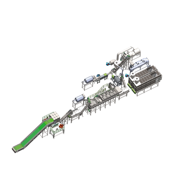
Overfeeding the crusher leads to rotor jams, excessive dust generation, and thermal degradation of the plastic. Conversely, underfeeding causes downstream starvation, reducing the overall efficiency of the line. Maintaining a consistent feed rate is essential for optimal crusher performance. Operators must utilize automated feeding systems, such as variable-speed belt conveyors linked to the crusher's motor amperage, to prevent surge loading.
Selecting the right rotor designs, blade geometries, and screen sizes is crucial. Heavy-wall rigid plastics require different cutting dynamics than high-tensile woven bags. Matching the crusher configuration to the specific feedstock ensures efficient size reduction and minimizes wear on cutting components. A staggered chevron rotor might be ideal for thick purgings, while an open-rotor design with aggressive hook blades is necessary for grabbing and shearing flexible films.
Success depends on aligning crusher screen sizes and motor power with the exact input requirements of the subsequent washing stage. This alignment ensures continuous, non-surge feeding, preventing bottlenecks and maintaining a steady flow of material into the friction washers and sink-float tanks. To achieve this, follow these specific operational steps:
Evaluating a washing system involves analyzing its friction washers, sink-float tanks, mechanical dewatering units, and thermal dryers. Each component must be sized to handle the target throughput while effectively removing specific contaminants like dirt, oil, and paper labels. A standard plastic washing line must be customized based on the exact contamination profile of the regional waste stream.
The washing line acts as the primary variable in the system. High contamination levels require longer residence times or more aggressive friction washing, effectively lowering the line's hourly throughput. Capacity planning must account for the worst-case contamination scenarios to prevent the washing stage from becoming a bottleneck. If a batch of agricultural film contains 30% sand by weight, the friction washers will require significantly more water and mechanical energy to clean the flake, reducing the forward flow rate.
The drying phase is the most critical bottleneck before extrusion. Residual moisture exceeding 1-2% causes steam generation within the extruder. This leads to surging, severe throughput drops, and porous pellets. Effective moisture control is the vital thermal link between washing and pelletizing. Mechanical dewatering presses must squeeze out the bulk of the water, followed by thermal pipeline dryers that utilize controlled heat to flash off the remaining surface moisture without melting the flake.
Different materials require different pelletizing solutions. Compactor-integrated pelletizers are ideal for low-density film flakes, providing necessary densification before extrusion. Single or twin-screw systems with force-feeders are better suited for rigid plastics. Selecting the right architecture is fundamental to achieving target capacities. A standard single-screw extruder will completely fail to process light film fluff without a massive crammer unit or an integrated cutter-compactor.
Matching the plastic pelletizing system melt capacity, degassing capabilities, and filtration area with the exact volume, bulk density, and moisture level of the washed flake is required. An undersized degassing system will fail if the input material has unexpectedly high moisture, drastically reducing throughput. The vacuum pumps must be sized to extract the specific volume of volatiles generated by the polymer and its residual contaminants.
There is an inverse relationship between pushing maximum mechanical throughput and maintaining high pellet quality. Forcing material through the extruder too quickly causes thermal degradation, polymer chain scission, and volatile-induced porosity. Balancing speed with quality is the core challenge of extrusion operations. Operators must monitor melt temperature, melt pressure, and specific energy input (SEI) to ensure the polymer is being plasticized gently rather than sheared to destruction.
Direct, unbuffered machine-to-machine feeding often fails due to micro-stoppages. A brief pause to change a screen on the pelletizer forces the entire upstream washing and crushing line to halt if there is no buffer. This start-stop operation destroys overall line efficiency, increases wear on heavy motors, and leads to inconsistent material processing temperatures.
Stable conveying solutions require sizing pneumatic conveying, screw augers, and belt conveyors specifically for the physical state of the material. Dense scrap flows easily, while high-volume, low-density fluffy flakes require specialized handling to prevent bridging and blockages. Piping diameters must be calculated based on the air velocity required to keep the specific flake size suspended without causing excessive abrasion on the pipe elbows.
Sizing intermediate buffer silos with active anti-bridging discharge systems between the washing line and the pelletizer absorbs upstream maintenance or downstream screen-filter changes. This allows the crusher and washer to run continuously, maximizing their utilization rates. A properly sized silo should hold at least two hours of extruder capacity, providing operators enough time to perform routine maintenance on the pelletizer without shutting down the wet section of the plant.
Unexpected spikes in dirt, paper, or mixed polymers impact the capacity of the entire line. A sudden influx of highly contaminated material requires slower processing through the friction washers, instantly reducing the feed rate to the pelletizer. If the system is rigidly coupled, this slowdown cascades through the entire facility, destroying the daily production targets.
Designing bypass loops, water filtration recycling loops, and variable speed drives (VSDs) on feeding systems allows operators to adjust flow rates dynamically. This system flexibility ensures that the line can adapt to changing feedstock conditions without suffering complete shutdowns. Advanced facilities utilize optical sorters and continuous melt filters to handle these spikes automatically, maintaining a steady output even when the input quality degrades.
| Material Type | Input Bulk Density (kg/m³) | Post-Crush Density (kg/m³) | Expected Yield Loss (%) | Required Buffer Capacity (Hours) |
|---|---|---|---|---|
| Rigid HDPE Bottles | 30-50 (Baled) | 350-450 | 10-15% | 1.5 |
| LDPE Agricultural Film | 150-200 (Baled) | 50-80 | 25-40% | 3.0 |
| PP Woven Bags | 100-150 (Baled) | 60-90 | 15-25% | 2.5 |
| PET Beverage Bottles | 250-300 (Baled) | 250-350 | 15-20% | 2.0 |
Sourcing the crusher, washer, and pelletizer from a single manufacturer simplifies integration and provides a single point of accountability. However, integrating specialized machines from different vendors might offer superior performance for specific stages. The decision depends on internal engineering capabilities and project risk tolerance. A facility with a strong in-house maintenance and engineering team can successfully integrate best-of-breed components, while a newer operation should rely on a turnkey provider.
Ensuring control-system integration is vital when mixing brands. PLC communication protocols must align, and interlocking emergency stops must function seamlessly across the entire line to protect personnel and equipment during a fault. If the extruder trips on high pressure, the upstream buffer silo discharge must stop immediately to prevent material overflow and potential fire hazards.
Demand technical data from any prospective plastic washing line manufacturer. Request mass balance flowcharts, energy consumption metrics per kilogram, guaranteed moisture content post-drying, and wear-rate metrics for abrasive contaminants. Verifiable data separates capable vendors from those making empty promises based on theoretical calculations.
Beware of vendors who overpromise capacity based on clean, rigid material when your primary feedstock consists of highly contaminated agricultural films. If the performance guarantees do not match your specific input material, the line will fail to meet production targets. Always demand a material trial using your exact bales before signing off on the final equipment design.
Buying a massively oversized crusher wastes capital expenditure and increases ongoing electrical costs due to running a large motor under light loads. Conversely, an undersized dryer creates an operational nightmare, bottlenecking a high-capacity pelletizer and reducing the output of the entire facility. Component sizing must be balanced across the entire process flow to ensure capital is deployed efficiently.
Capacity planning requires a precise understanding of the weakest link in the chain. Upgrading the pelletizer without upgrading the drying capacity of the washing line yields zero increase in final output. Engineers must identify the true bottleneck—whether it is thermal, mechanical, or volumetric—and direct capital upgrades specifically to that constraint.
Balanced capacity reduces energy spikes and minimizes idle running time. When machines operate at their designed continuous load, thermal efficiency improves. This lowers the overall cost-per-ton of recycled pellets and improves the facility's profit margins. Running a 500 kW extruder motor at 40% load because the washing line cannot keep up is a massive waste of electrical energy.
Mismatched equipment forces machines to cycle on and off, or run partially empty, which wastes energy and increases wear on contactors and drive belts. Optimizing the thermal efficiency of the extruder relies heavily on receiving a consistent, well-prepared feed from the upstream components. Stable input allows the extruder to run in a steady state, maximizing the output per kilowatt-hour consumed.
A: Start with the target output of high-quality pellets. Reverse-calculate by factoring in expected yield losses from dirt, labels, and moisture extraction. Size upstream washing and crushing equipment to match those specific volume and mass requirements, ensuring the pelletizer receives adequate feed.
A: Throughput drops are often caused by high moisture content from the washing line, low bulk density of the feed material, inadequate force-feeding mechanisms, or mismatched motor torque for the specific polymer formulation being processed.
A: Silos decouple the continuous operation of the crusher and washer from the intermittent stoppages of the pelletizer. They prevent system-wide shutdowns during routine maintenance, like screen changes, by storing processed flake until the extruder is ready.
A: Crushers output high-volume, low-density fluff, especially from films. This fluffy material must be densified, compacted, or force-fed into the pelletizer. Without proper densification, the extruder starves, leading to unstable throughput and poor pellet quality.
A: Look for custom engineering capabilities, transparent mass balance calculations, and proven moisture reduction guarantees. They should offer material-specific trial runs and demonstrate the ability to seamlessly interface control systems with downstream extrusion lines.


