
- All
- Product Name
- Product Keyword
- Product Model
- Product Summary
- Product Description
- Multi Field Search
 English


Views: 0 Author: Site Editor Publish Time: 2026-10-24 Origin: Site


Walk onto the floor of any high-yield industrial recycling facility, and the first thing you notice is the intense heat and the relentless hum of heavy machinery. Beneath the thick steel casings of these machines, raw and irregular plastic scrap is undergoing a violent thermodynamic transformation. It is being converted into valuable, everyday manufacturing feedstock. Yet, many facility managers and newcomers to the polymer sector struggle to grasp the exact mechanical physics happening inside the barrel.
If you plan to upgrade a production line or build a profitable recycling plant from scratch, understanding the internal mechanics of extrusion is your absolute first step. In this engineering guide, we will break down the precise operational workflow, examine the vital structural components, and explore how modern heavy-duty systems process the most stubborn post-consumer materials.
At its core, an industrial extruder is a highly engineered, continuous pump. It is designed to melt, homogenize, and force raw thermoplastic materials through a restrictive metal shaping tool. While this mechanism is used in food production and metallurgy, it remains the undisputed backbone of global plastic manufacturing and resource recovery.
The primary job of this equipment is to transform solid polymer flakes or pellets into a homogenous, honey-like liquid. Novice operators often assume the external heater bands do all the melting. In reality, external heat only starts the process. The vast majority of the thermal energy is generated by internal friction. As the rotating screw forces the plastic against the hardened barrel walls, the mechanical shear creates immense heat. Once the polymer reaches the correct viscosity, the machine pushes this pressurized liquid through a die block to form a continuous profile.
Looking at current industry trends, the extrusion landscape is undergoing a massive technological shift. Driven by strict global circular economy mandates and rising electricity costs, modern facilities are abandoning outdated manual systems. We are seeing rapid adoption of smart extrusion technology. Plant engineers are now integrating real-time melt pressure sensors, automated gravimetric dosing, and permanent magnet synchronous motors. This data-driven approach drastically cuts energy waste and minimizes the carbon footprint of the entire recovery process.
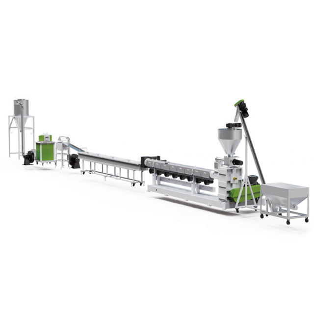
To fully troubleshoot production defects, you must understand the anatomy of your equipment. An extruder is a series of integrated mechanical zones working in unison. A failure in one zone immediately cascades down the line.
The hopper is the material entry point. Located at the rear above the feed throat, it relies on gravity to drop flakes into the barrel. On the factory floor, operators listen closely to this area. A steady, rhythmic crunching sound indicates good flow. If the material is exceptionally light or fluffy, engineers will install mechanical force-feeders to physically cram the plastic into the screw flights and prevent bridging.
This heavy-duty cylindrical chamber houses the screw. Because it endures internal pressures exceeding several thousand PSI and the constant abrasive scouring of dirty flakes, it is cast from bimetallic hardened steel alloys. The exterior is wrapped in ceramic or infrared heater bands divided into independent temperature zones. The thermal profile is programmed to increase gradually from the feed throat to the die head. This prevents sudden thermal shock and polymer degradation.
The screw is the beating heart of the operation. As it rotates, it conveys, compresses, and plasticizes the polymer. A standard profile is divided into three distinct geometric sections. The feed section features deep spiral threads to aggressively bite the raw material. Moving forward, the transition section features a decreasing channel depth. This squeezes the plastic tightly, generating the extreme shear friction required for melting. Finally, the metering section utilizes very shallow threads to iron out temperature variations and build the immense pressure needed for pumping.
Pushing highly viscous liquid through a restricted metal pipe requires brutal rotational force. The drive system pairs a high-efficiency electric motor with a heavy-duty reduction gearbox. The gearbox lowers the motor speed while multiplying the torque. More importantly, it houses a massive thrust bearing assembly. As the screw violently pushes the plastic forward, the plastic pushes back. The thrust bearing absorbs this severe backward force, protecting the motor from catastrophic destruction.
For plant managers looking to optimize throughput, mastering the sequential workflow is critical. The process follows a strict thermodynamic path.
The cycle begins when raw flakes drop through the feed throat into the rotating screw flights. Maintaining a steady volumetric flow rate here is essential. Any interruption or material bridging will cause immediate pressure drops at the die head, leading to broken strands or uneven product dimensions.
As the massive drive motor turns the shaft, the plastic moves forward into the transition zone. Here, the true physics of extrusion take over. The decreasing depth of the screw channels subjects the solid flakes to extreme mechanical shear. This internal friction converts the noisy, solid plastic into a silent, uniform melt.
When dealing with post-consumer scrap, residual moisture and surface printing inks are unavoidable. As these contaminants hit the high-heat zones, they instantly vaporize into volatile gases. If these gases remain trapped, the final product will be structurally weak and full of hollow bubbles. To solve this, modern barrels feature a specialized decompression zone. The screw channels suddenly deepen, dropping the internal pressure. A high-powered vacuum pump then forcefully extracts the trapped moisture and gas through a top-mounted vent.
Once fully degassed, the clean melt enters the high-pressure metering zone. The screw acts as a pump, forcing the liquid through a hydraulic screen changer. Fine metal mesh filters trap microscopic aluminum flakes, paper fibers, or un-melted dirt. The purified polymer is then pushed through the die, emerging into the open air ready for immediate cooling and shaping.
While traditional manufacturing uses this technology to create finished goods like PVC pipes, the recycling sector uses it for material standardization. Shredded post-consumer plastic is bulky, chaotic, and notoriously difficult to feed into standard injection molding machines. A specialized plastic pelletizing machine solves this logistical nightmare by converting scrap into uniform, dense resin cylinders.
The workflow starts identically by melting and filtering the scrap. But instead of shaping a pipe, the die head is machined with dozens of tiny circular holes. The machine extrudes continuous, glowing-hot spaghetti strands. These strands are immediately pulled through a long circulating water trough. The rapid temperature drop solidifies the polymer, giving it the necessary tensile strength. After passing through high-velocity air knives to blast away surface water, the strands enter a rotary cutter. Whirling blades chop the plastic into perfect, uniform pellets that are classified by vibration and bagged for resale.
Flexible agricultural films and rigid logistics crates behave very differently under heat and pressure. Dense materials like Polypropylene and High-Density Polyethylene originate from heavy-duty items like shampoo bottles, automotive battery casings, and industrial pipes.
Processing these dense polymers requires uncompromising, high-torque equipment. Forward-thinking facility owners achieve profitability by investing in a dedicated Rigid Plastic Pelletizing Line engineered specifically for high bulk densities.
Rigid flakes present unique processing challenges. They carry a higher volume of stubborn surface contaminants, including strong adhesives and heavy printing inks. When these enter the barrel, they generate massive volumes of gas. If the vacuum system is undersized, the resulting pellets will be riddled with microscopic voids, rendering them useless for high-end injection molding.
When designing a plant layout, engineers must evaluate the moisture and contamination levels of their input material to choose the correct machine architecture. Below is a practical comparison of the two primary configurations used in the industry.
| System Architecture | Ideal Material Profile | Engineering Characteristics | Primary Advantage |
|---|---|---|---|
| Single-Stage Extrusion | Clean, dry post-industrial scrap with minimal printing. | Utilizes one long continuous barrel. Length-to-Diameter ratio typically ranges from 32 to 36. Single vacuum venting port. | Highly energy-efficient, requires a smaller factory footprint, and offers lower maintenance costs. |
| Double-Stage Extrusion | Dirty, heavily printed post-consumer waste with high moisture content. | Mother-baby configuration. Primary high-speed extruder feeds directly into a larger, slower secondary extruder. Dual vacuum zones. | Provides massive surface area for ultra-fine filtration and aggressive secondary degassing, guaranteeing void-free pellets. |
Procuring industrial machinery is a massive capital expenditure. Plant managers must rigorously match equipment specifications to their exact material streams. A mismatch here leads to frequent thrust bearing failures, poor output quality, and severe financial losses.
There is no universal screw design. The geometry must be mathematically tailored to your polymer melt flow index and bulk density. When configuring a Pelletizing system for rigid plastic, demand specific parameters. Look for systems capable of stable outputs ranging from 300 to 1000 kilograms per hour, depending on your target capacity.
Filtration technology is another critical checkpoint. Standard manual screen changers force operators to halt the machine to swap clogged filters. This downtime is unacceptable in a 24/7 operation. Specify continuous dual-piston hydraulic screen changers. These advanced units allow operators to swap screens on the fly without dropping melt pressure or breaking strands.
Finally, evaluate the drive motor efficiency. High-output demands require exponentially more electricity. Specify permanent magnet synchronous motors. They deliver superior low-RPM torque and can reduce energy consumption by up to 30% compared to traditional asynchronous motors. As a standard engineering practice, size your gearbox to run comfortably at 80% capacity. This single decision will double the lifespan of your internal thrust bearings.
Understanding the thermodynamic mechanics of extrusion demystifies the complex world of industrial recycling. Every component, from the bimetallic barrel to the hydraulic screen changer, plays a critical role in maintaining continuous, profitable production.
Success on the factory floor comes down to precise equipment matching. Whether you are processing clean industrial offcuts or heavily contaminated post-consumer rigid flakes, aligning your machine's torque and degassing capabilities with your material is non-negotiable. If you are ready to scale your operations, reduce energy overhead, and produce premium-grade resin, explore the customized, heavy-duty solutions available at Jwell Recycling to build a line that runs flawlessly shift after shift.
Its primary function is to apply mechanical shear friction and controlled heat to melt solid raw plastics. It acts as a massive high-pressure pump, forcing the viscous, homogenized melt through a restrictive die to create continuous profiles like pipes, sheets, or strands for pelletizing.
Operating temperatures depend entirely on the specific polymer being processed. For example, Low-Density Polyethylene usually runs between 160 to 200 degrees Celsius, while engineering plastics like Polycarbonate may require thermal profiles exceeding 280 to 300 degrees Celsius. The barrel is divided into multiple heating zones to gradually reach these targets.
Routine maintenance focuses heavily on lubrication and alignment. Plant engineers must regularly check the gearbox oil levels, inspect the thrust bearings for unusual vibrations, and calibrate the thermal sensors. Additionally, operators must pull and clean the screw periodically to remove degraded carbon buildup that can contaminate future batches.
A single-stage setup uses one continuous barrel and is engineered for clean, dry scrap. A double-stage setup connects two machines in sequence. The first machine melts and performs a coarse filtration, while the second, slower machine provides a massive surface area for ultra-fine filtration and secondary vacuum degassing. This makes the double-stage ideal for wet, highly printed post-consumer waste.
The system forces the purified melt through a die head to form long continuous strands. These hot strands are immediately pulled through a cold water trough to solidify them. After high-speed air knives strip away residual moisture, the hardened strands are fed into a rotary cutter where spinning blades chop them into uniform, cylindrical pellets.
Rigid materials like crushed bottles and battery casings have high bulk densities and heavy contamination. A system built for this features bimetallic hardened barrels, customized high-shear screw geometries, oversized thrust bearings, and robust dual-vacuum degassing zones capable of extracting massive volumes of vaporized inks and moisture.
Extrusion is a continuous, non-stop process that pushes melted material through an open-ended die to create long, uninterrupted shapes. Injection molding is a cyclical, stop-and-go process. It injects a precise, measured shot of melted plastic into a closed metal mold, holds it under pressure to cool, and ejects a discrete, three-dimensional part like a bottle cap or automotive gear.


