- All
- Product Name
- Product Keyword
- Product Model
- Product Summary
- Product Description
- Multi Field Search
 English


| Quantity: | |
|---|---|


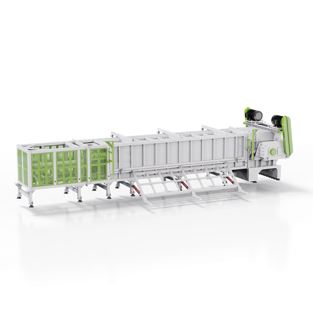
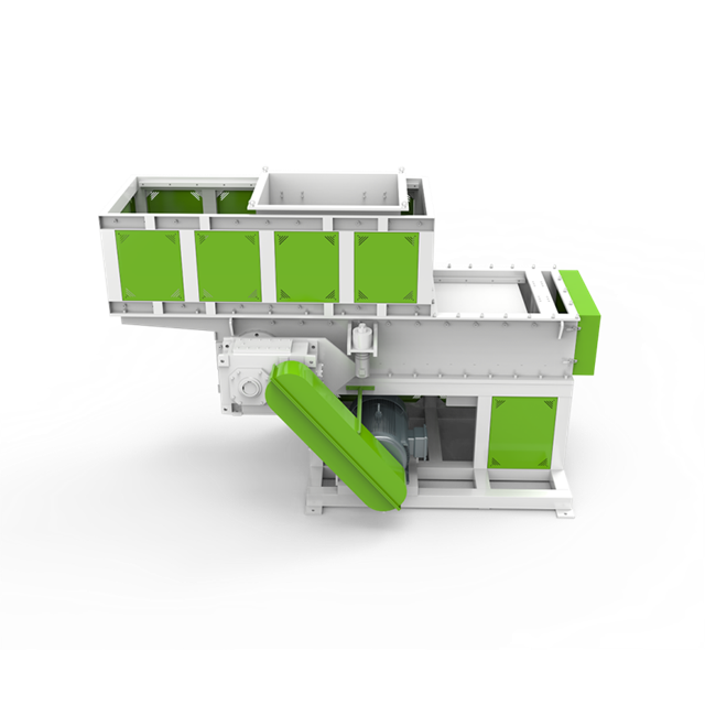
The DYTSS Series Two-Shaft Shredder reduces large plastic waste using a dual-shaft cutting structure. Three models list rotor diameter, paired drive power, cutter count and blade thickness.
The two-shaft structure offers a defined approach to reducing larger plastic items before further recovery. Selection should relate the incoming shape and wall thickness to the working chamber, rotor and knife arrangement. Three sizes provide blade diameter and thickness, cutter counts and paired drive data, while the control description includes reversing and protective functions. Buyers can compare these structural points without assuming a production rate that is not supplied in the model table. The low-speed cutting description and service-related knife features are relevant to the operating discussion, but do not establish universal wear-life or output-size promises. A useful project specification identifies the bulky plastic stream, loading method and required discharge condition, then sets the boundary between shredding and any later cleaning, secondary reduction or pelletizing equipment.

Plastic barrels, pallets, basins, drums, chairs and PC water bottles are identified applications. Define the actual item dimensions and construction. The feed assessment should include attachments and contamination rather than treating all bulky objects as equivalent cutting loads.
Large items need an entry description covering shape, thickness and attached components. A chamber comparison based only on overall length leaves important details unresolved. Provide photographs and measurements of representative pieces so the cutting duty reflects the normal stream as well as difficult occasional items.
Two rotating cutting assemblies tear and reduce material at low speed. The product describes high-torque cutting for large waste plastics. This arrangement provides an industrial reduction step, with the required downstream material condition established separately.
The two shafts define the cutting structure. Selection should still consider rotor diameter, blade geometry and chamber space together with the intended waste. Shaft count alone cannot establish the required discharge size or make one arrangement universally suitable for every bulky plastic feed.
DYTSS-32100 lists 40 mm blade thickness. DYTSS-40130 and DYTSS-50180 list 50 mm. These figures describe the cutters and should not be presented as the final fragment dimensions.
Blade thickness changes between the listed arrangements and describes the cutter itself. Keep that dimension separate from the target size of discharged material. Defining both allows the proposal to address the mechanical selection and the condition needed by the next recovery process without confusing their meanings.
MODEL | Rotor Dia(mm) | Drive Power (kw) | Rotor Blade (pcs) | Blade Thickness (mm) | Crushing Chamber Size Max(mm) |
DYTSS-32100 | Ф430 | 22*2 | 26 | 40 | 1000×800 |
DYTSS-40130 | Ф514 | 37*2 | 26 | 50 | 1300×950 |
DYTSS-50180 | Ф615 | 55*2 | 36 | 50 | 1800×1200 |
The drive entries are 22*2, 37*2 and 55*2 kW. Rotor diameters increase from Ф430 to Ф615 mm. Review both values with the material's strength and size instead of selecting only the most powerful model.
Paired motor ratings should remain paired in the equipment specification. Review them with the selected rotor and chamber, then identify any additional handling loads. A drive entry should not be presented as complete installed power for a shredding station containing conveyors, collection or other auxiliaries.
The described PLC controls include start, stop, reverse and overload protection. Short-circuit and phase-loss protection are also identified. Agree the final electrical control scope as part of the supplied equipment configuration.
Protective functions belong in the selected control arrangement. Discuss normal feeding, difficult loads and the operator interface alongside PLC reversing and the stated protections. The control description supports equipment review but does not replace the need to establish suitability for the actual plastic material.
The blade description identifies alloy steel, a hexagonal inner hole and repairable cutters. These features relate to torque transmission and knife handling. Define the proposed knife arrangement and access requirements for the intended waste before finalizing the machine layout.
Knife dimensions and counts change through the range, so the service discussion should begin with the delivered cutter set. Record blade diameter, thickness and the selected arrangement in the equipment documentation. The stated repair-related construction can then be reviewed alongside spare-knife identification and the access needed to inspect and work on the cutting area.
The DYFSS four-shaft shredder offers a different multi-shaft route. The DYSSJ single-shaft shredder provides a hopper-and-pusher-focused option. Compare the feeding method and discharge requirement as well as the number of shafts.
Different shaft arrangements should be compared with the same incoming items and downstream requirement. Chamber, cutter and loading data provide a stronger basis than shaft count alone. The comparison should explain the intended reduction duty and supply scope rather than assume that one structure is always better.
Provide DYUN's shredder engineers the polymer, item photographs, largest dimensions and planned input. Add the next recycling step and desired fragment form. This allows the chamber and cutter configurations to be assessed against the intended operation.
Because the model table does not provide a kg/h rating, the requested duty should be reviewed directly with representative material. Include the loading method and desired discharge condition. This gives any performance discussion a defined basis instead of deriving an unsupported production figure from the paired motor ratings.
The DYUN company profile describes its position in JWELL's waste plastic equipment activities. DYTSS proposals should define the incoming bulky waste and the dual-shaft cutter arrangement before assigning the machine to a wider recycling route.
For two-shaft projects, material geometry and the requested discharge condition should lead the manufacturer discussion. The proposal can then identify the paired drives, chamber and knife arrangement, together with loading and collection scope. A clearly described duty is particularly important where no model-specific hourly output is published.

Two shafts form the cutting structure, with model-specific rotor, blade and chamber data. Review those entries with the size and thickness of the incoming plastic. Shaft count alone does not determine suitability or the discharged material size.
The listed thicknesses are 40 and 50 mm. They describe the cutters, not guaranteed output dimensions. The required discharge condition should be stated separately and assessed with the full cutting arrangement.
The model table does not provide a kg/h rating. Discuss the requested duty with the actual material, loading method and selected configuration. Motor power and blade thickness should not be used to invent a production figure.
The description includes PLC reversing, overload, short-circuit and phase-loss protection. Confirm the delivered control arrangement in the proposal and consider it alongside feeding conditions. These functions do not replace a material-suitability assessment.
Provide normal and difficult item dimensions, wall thickness and polymer information. Specify loading and collection requirements, plus the condition needed by the next process. The quotation should identify the selected cutting arrangement and any surrounding handling equipment.
Request identification of the delivered knife arrangement, blade dimensions and compatible replacement parts. Clarify service requirements and the scope of any spare set in the quotation. A repair-related feature should not be treated as a fixed lifetime or replacement guarantee.